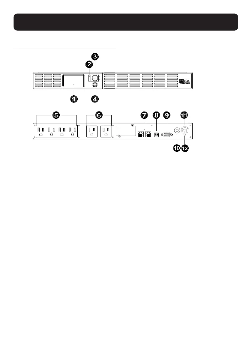
FRONT / REAR PANEL DESCRIPTION
1. LCD module display
LCD shows all the UPS information with icons and messages.
2. Power On Indicator
This LED is illuminated when the utility condition is normal and the UPS outlets are providing power,
free of surges and spikes.
3. Power Switch
Master on/off switch for equipment connected to the battery power supplied outlets.
4. LCD function selected switch
The switch can be used to select the LCD display contents Including input/output voltage and estimated
run time, etc.
5. Battery and Surge Protected Outlets
The unit has four battery powered/surge suppression outlets for connected equipment to ensure
temporary uninterrupted operation of your equipment during a power failure. (DO NOT plug a laser
printer, paper shredder, copier, space heater, vacuum cleaner, sump pump or other large electrical
devices into the “Battery and Surge Protected Outlets”. The power demands of these devices may
overload and damage the unit.)
6. Full-Time Surge Protection Outlets
The unit has two surge suppression outlets.
7. Communication Protection Ports RJ45
Communication protection ports, bi-directional, will protect a 10/100/1000Ethernet connection. (RJ45).
8. USB Port to PC
This port allows connection and communication from the USB port on the computer to the UPS unit.


 To Next Page