40 Series
18
5. ELECTRICAL CONNECTIONS
Make sure that you can see the roof while operating
the switch!
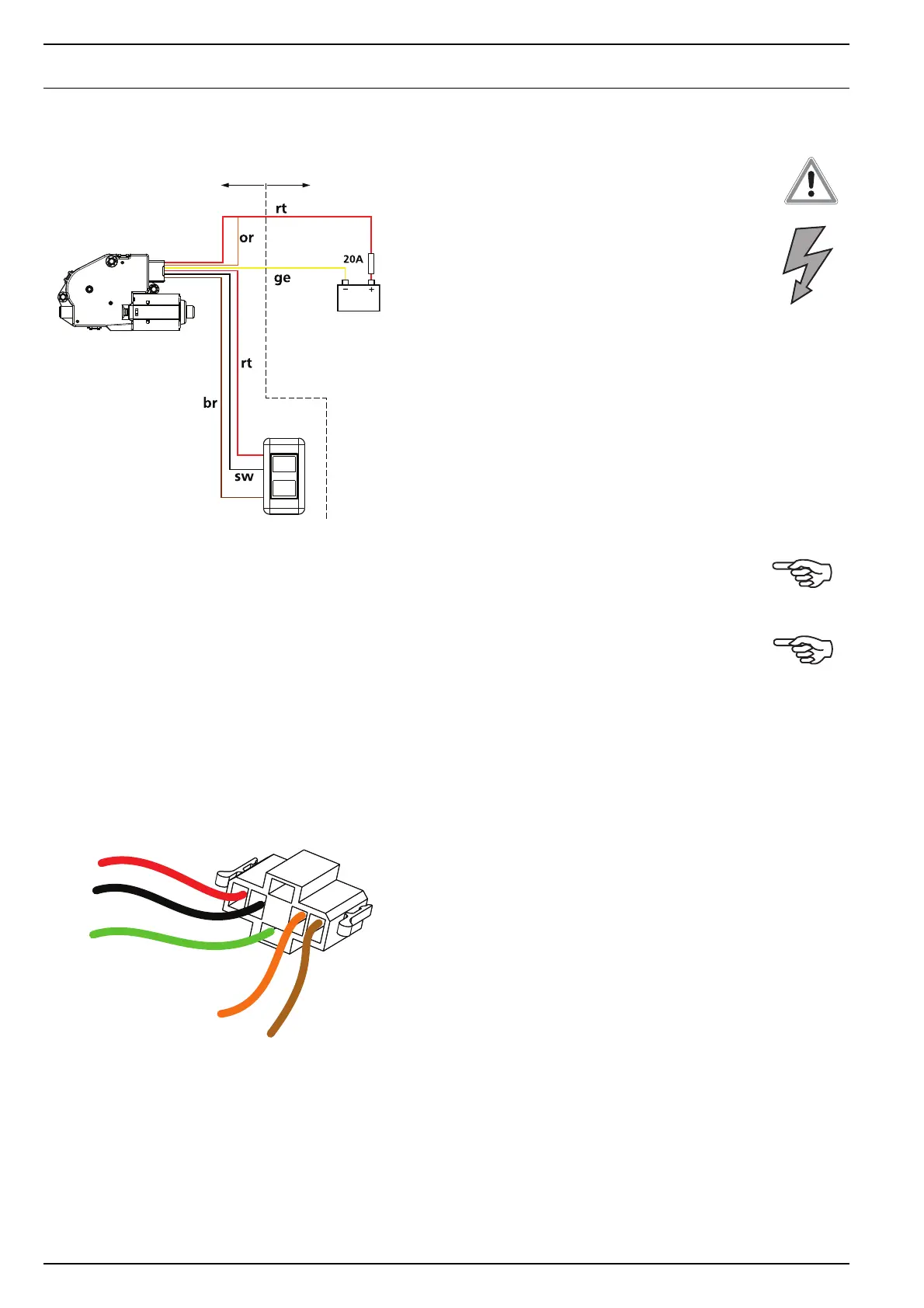
Determine switch position and install it.
Connect battery 12 V DC.
Red: + 12 V DC, continuous,
with fuse 20 A.
Yellow: – (minus)
br = brown
ge = yellow
or = orange
rt = red
sw = black
Attach connector wiring harness to motor.
See electrical diagram (chapter 7.)
Note:
Ensure there is at least 20 A available.
Note:
In case there’s a 24 V DC power supply, use a 24 V -
12 V DC convertor that can handle at least 20 A.
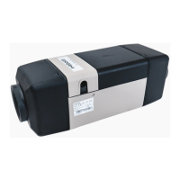
2 additional connections are necessary for switch
illumination (see illustration):
- Orange: + 12 V DC
- Green: – (minus)
Other wires:
- Red: Motor close
- Black: Motor – (minus)
- Brown: Motor open
br = brown
gn = green
or = orange
rt = red
sw = black
sw
gn
or
rt
br
customerWebasto





 To Next Page