EasyManua.ls Logo

Webasto Air Top 5000 User Manual

Webasto Air Top 5000
32 pages
To Next Page IconTo Next Page
Page #1 background imageLoading...
Page #1 background image
Table of Contents
1. Introduction
1.1 Scope and Purpose . . . . . . . . . . . . . . . . . . . . . . . . . . . . . . . . . . . . . . . . . . . . . . . . . . . . . . . . . . . . 1-1
1.2 Meaning of Warning, Caution and Notation Headings . . . . . . . . . . . . . . . . . . . . . . . . . . . . . . . . . . 1-1
1.3 Additional Documentation to be Used . . . . . . . . . . . . . . . . . . . . . . . . . . . . . . . . . . . . . . . . . . . . . . 1-1
1.4 General Safety Regulations and Information . . . . . . . . . . . . . . . . . . . . . . . . . . . . . . . . . . . . . . . . . 1-1
1.4.1 General Safety Notes . . . . . . . . . . . . . . . . . . . . . . . . . . . . . . . . . . . . . . . . . . . . . . . . . . 1-1
2. General Description
2.1 General Description . . . . . . . . . . . . . . . . . . . . . . . . . . . . . . . . . . . . . . . . . . . . . . . . . . . . . . . . . . . 2-1
3. Functional Description
3.1 Operating the Air Top 5000 with Self Diagnostic Control Unit . . . . . . . . . . . . . . . . . . . . . . . . . . . . . 3-1
3.1.1 Heater Control Element . . . . . . . . . . . . . . . . . . . . . . . . . . . . . . . . . . . . . . . . . . . . . . . . . 3-1
3.1 2 Switch-On . . . . . . . . . . . . . . . . . . . . . . . . . . . . . . . . . . . . . . . . . . . . . . . . . . . . . . . . . . 3-2
3.1.3 Heating Operation . . . . . . . . . . . . . . . . . . . . . . . . . . . . . . . . . . . . . . . . . . . . . . . . . . . . 3-2
3.1.4 Switch-Off . . . . . . . . . . . . . . . . . . . . . . . . . . . . . . . . . . . . . . . . . . . . . . . . . . . . . . . . . . 3-2
3.1.5 Switch-Off upon Malfunction . . . . . . . . . . . . . . . . . . . . . . . . . . . . . . . . . . . . . . . . . . . . 3-3
3.2 7-Day Digital Timer Model 1531 with 3 Time-Settings and Temperature Selector . . . . . . . . . . . . . . . 3-3
4. Technical Data
4.1 General Information . . . . . . . . . . . . . . . . . . . . . . . . . . . . . . . . . . . . . . . . . . . . . . . . . . . . . . . . . . . 4-1
4.2 Dimensions . . . . . . . . . . . . . . . . . . . . . . . . . . . . . . . . . . . . . . . . . . . . . . . . . . . . . . . . . . . . . . . . . 4-2
5. Installation
5.1 General Information . . . . . . . . . . . . . . . . . . . . . . . . . . . . . . . . . . . . . . . . . . . . . . . . . . . . . . . . . . . 5-1
5.2 Installation Location . . . . . . . . . . . . . . . . . . . . . . . . . . . . . . . . . . . . . . . . . . . . . . . . . . . . . . . . . . . 5-1
5.3 Mounting the Air Top 5000 Heater . . . . . . . . . . . . . . . . . . . . . . . . . . . . . . . . . . . . . . . . . . . . . . . . 5-2
5.4 Exhaust System . . . . . . . . . . . . . . . . . . . . . . . . . . . . . . . . . . . . . . . . . . . . . . . . . . . . . . . . . . . . . . 5-4
5.5 Combustion Air Supply . . . . . . . . . . . . . . . . . . . . . . . . . . . . . . . . . . . . . . . . . . . . . . . . . . . . . . . . . 5-5
5.6 Fuel System . . . . . . . . . . . . . . . . . . . . . . . . . . . . . . . . . . . . . . . . . . . . . . . . . . . . . . . . . . . . . . . . . 5-5
5.6.1 General Information . . . . . . . . . . . . . . . . . . . . . . . . . . . . . . . . . . . . . . . . . . . . . . . . . . . 5-5
5.6.2 Fuel System Limits . . . . . . . . . . . . . . . . . . . . . . . . . . . . . . . . . . . . . . . . . . . . . . . . . . . . . 5-5
5.6.3 Fuel Standpipe . . . . . . . . . . . . . . . . . . . . . . . . . . . . . . . . . . . . . . . . . . . . . . . . . . . . . . . 5-6
5.6.4 Fuel Metering Pump . . . . . . . . . . . . . . . . . . . . . . . . . . . . . . . . . . . . . . . . . . . . . . . . . . . 5-7
5.6.5 Fuel Line . . . . . . . . . . . . . . . . . . . . . . . . . . . . . . . . . . . . . . . . . . . . . . . . . . . . . . . . . . . 5-7
5.6.6 Fuel Filter . . . . . . . . . . . . . . . . . . . . . . . . . . . . . . . . . . . . . . . . . . . . . . . . . . . . . . . . . . . 5-8
AIR TOP 5000 TABLE OF CONTENTS
I
Page

Other manuals for Webasto Air Top 5000

Question and Answer IconNeed help?

Do you have a question about the Webasto Air Top 5000 and is the answer not in the manual?

Webasto Air Top 5000 Specifications

General IconGeneral
Heating Power5 kW
Fuel TypeDiesel
Voltage12 V / 24 V
Heater TypeAir Heater
Noise Level42 dB
Operating Temperature Range-40°C to +40°C

Summary

Introduction

1.1 Scope and Purpose

Explains manual's intent for installation and servicing personnel.

1.2 Meaning of Warning, Caution and Notation Headings

Defines warning, caution, and attention notation meanings.

1.3 Additional Documentation to be Used

Mentions complementary documentation for installation.

1.4 General Safety Regulations and Information

Outlines general safety rules and information for operation.

1.4.1 General Safety Notes

Specific safety notes for heater installation and operation.

General Description

2.1 General Description

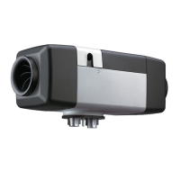
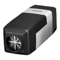
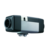
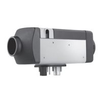
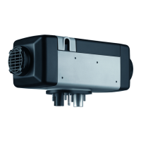
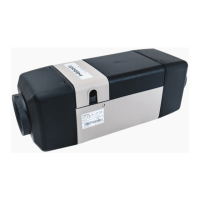
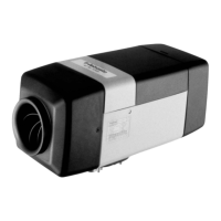
Overview of Air Top 5000 heater features, applications, and benefits.

Functional Description

3.1 Operating the Air Top 5000 with Self Diagnostic Control Unit

Details operation using the self-diagnostic control unit.

3.1.1 Heater Control Element

Explains the function and use of the heater control element.

Technical Data

4.1 General Information

Provides general technical specs and electrical component info.

4.2 Dimensions

Shows mounting dimensions and space requirements for the heater.

Installation

5.1 General Information

Guides through installation procedures for reliable operation.

5.2 Installation Location

Details criteria and considerations for selecting a suitable installation location.

5.3 Mounting the Air Top 5000 Heater

Details the process of mounting the heater.

5.4 Exhaust System

Details installation and routing for the exhaust system.

5.5 Combustion Air Supply

Covers guidelines for supplying combustion air to the heater.

5.6 Fuel System

Details the fuel system components and their installation.

5.6.1 General Information

Introduces the fuel metering pump, line, and standpipe importance.

5.6.2 Fuel System Limits

Details maximum suction and delivery limits for the fuel system.

5.6.3 Fuel Standpipe

Provides instructions for installing the fuel standpipe.

5.6.4 Fuel Metering Pump

Covers installation criteria for the fuel metering pump.

5.6.5 Fuel Line

Details fuel line installation and connection requirements.

5.6.6 Fuel Filter

Explains fuel filter installation and replacement.

5.7 Wiring Connections

Covers wiring connections for the heater.

5.7.1 General Information

Explains operating options with standard or digital timer.

5.7.2 Connector Identification

Identifies various connectors used in the heater's wiring system.

5.7.3 Wiring Diagram - Air Top 5000, 12 and 24 Volt

Presents the electrical wiring diagram for the heater.

5.7.4 Electrical Component Identification Table

Lists and identifies electrical components used in the system.

5.8 Control Element Installation

Details how to mount the control element.

5.8.1 Fuel Metering Pump Harness

Connects the fuel metering pump harness to the pump.

5.8.2 Remote Temperature Sensor (Optional)

Provides guidelines for installing the remote temperature sensor.

5.9 Ducting the System

Covers general information about ducting and its limitations.

5.9.1 General Information

Details ducting requirements, length, and bends.

5.10 Initial Start Up

Guides through the initial start-up procedures and checks.

Maintenance/Troubleshooting

6.1 Heater Maintenance

Outlines routine maintenance tasks for the heater.

6.2 Troubleshooting

Introduces troubleshooting steps and contact info for issues.

6.2.1 Heater Shuts Off Automatically

Describes automatic shut-off due to malfunctions and reset procedures.

6.2.2 Heater Emits Black Smoke from Exhaust

Advises checking air intake and exhaust for obstructions or damage.

6.2.3 Self-Diagnostic System (Reading Flash Codes)

Explains how to read and interpret diagnostic flash codes.

6.2.4 Diagnostic Code Table

Lists symptoms, causes, and corrections for diagnostic codes.

Related product manuals