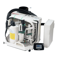
CC8 roof-top air-conditioning system 4 Installation instructions
403
4.6 Required equipment, special tools and accessories
• For installation
– Sheet metal cutter for cut-outs in the vehicle/cab roof
– Mechanics tool kit
– Clip pliers to install the refrigerant hoses
– Hose shears
• For evacuating, filling and checking the refrigerant circuit
– Servicing / recycling station for R134a refrigerant
– Vacuum pump, intake rate min. 5 m
3
/h, final pressure 1 Torr
– Filler hoses with fast-action connector for R134a
– Leak detector
– Digital thermometer
– Bottle of R134a refrigerant
– Recycling bottle for R134a refrigerant
– R134a bottle connectors
– Refrigeration oil ZXL PAG 100 for Seltec compressor
– Test fittings with intake pressure and high pressure gauges
– Spring balance or scales (min. 35 kg)
– Nitrogen bottle with pressure reducer.
4.7 Preparations on vehicle/cab roof
The method of installation depends on the type of vehicle. It is therefore essential to refer to the vehicle manufacturer's
instructions. In addition, the best position for installation must be selected to suit the contours of the roof.
Fig. 401 shows the installation dimensions and the mounting hole pattern for the roof-top unit. The cut-out for the air
outlet is off-centre in the base plate. This must be taken into account when positioning the system and the air
distribution panel and when making the opening for the intermediate ceiling.
CAUTION
• Be careful not to damage and supporting structures (for example roof bows and
reinforcements) or interior fittings, such as screws, mounting brackets or stiffening
frames on roof bows.
• Reinforcing roof bows and large washers should be used if necessary to install the
air-conditioning system safely.
1. Remove the intermediate roof layer and any insulation material from the area around the air ducts.
2. Sketch the air duct cut-outs and holes for condensation hoses (hatched areas in Fig. 401) on the roof, using a
template for the roof section (optional, part No. 98500) if necessary.
3. Align the template or roof-top unit (without cover) and drill six holes with a diameter of 10 mm.
4. Remove the template or roof-top unit.
5. Deburr/smooth the edges of cut-outs and holes and treat them with anti-corrosive paint.
6. Install any roof reinforcements or additional frames required in the vehicle for safe installation of roof-top unit (not
supplied).
An installation kit including these roof reinforcements is available for Mercedes Benz Sprinter and Volkswagen LT
vans/buses with a medium and long wheelbase and with a high roof, from model year 1996 onwards. Do not use
the template mentioned in step 2 in this case.
7. Prepare the interior of the roof so that the air ducting system or air distribution panel can be mounted on the
underside of the roof.
8. Match spacers to the shape of the roof.

 Loading...
