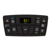
4 Installation instructions CC8 roof-top air-conditioning system
408
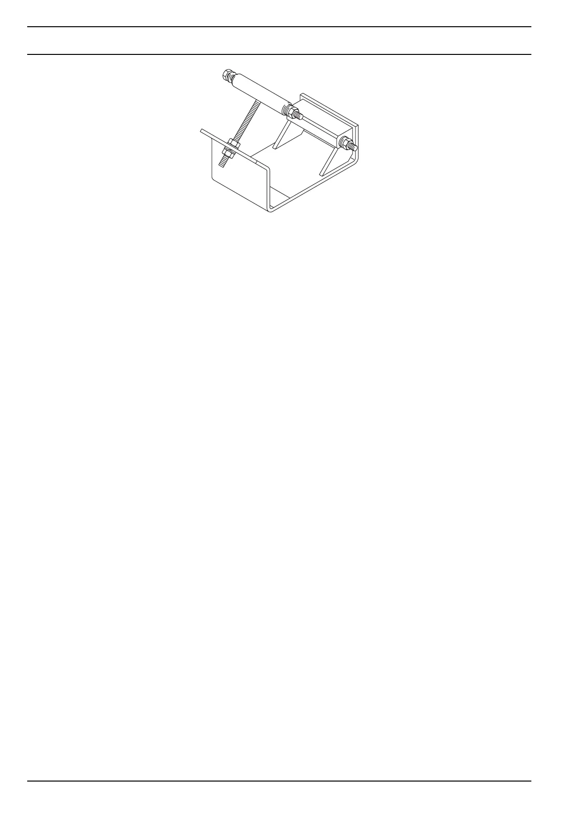
Fig. 403 Universal compressor mounting bracket
NOTE
Use shims to compensate for tolerances exceeding 0.3 mm between compressor
mounting bracket and each flange hole on the compressor.
4.9 Manufacture of hose lines
1. Select/determine location/routing of the hose lines (bear the diameter of screwed connections at cut-outs in mind).
2. Cutting hoses to size
– Measure the hose lengths in the vehicle; make sure there are no sharp bends/kinks (do not exceed the minimum
bending radius).
– Refrigerant hose NW 16 (intake side) should be insulated to prevent the formation of condensation (not included
in installation kit).
NOTE
The minimum bending radius for clip connections and refrigerant hose GH134:
Bending radius refrigerant hose NW 12 (R min.: 75 mm)
Bending radius refrigerant hose NW 16 (R min.: 100 mm)
Minimum bending radius for clip connections and refrigerant hose FC 802:
Bending radius refrigerant hose NW 12 (R min.: 89 mm)
Bending radius refrigerant hose NW 16 (R min.: 115 mm)
NOTE
When routing the hoses be sure to avoid narrow bends in vertical direction as
refrigerator oil may collect in these bends. This may result in inadequate oil circulation
and thus in damage to the compressor, even if the minimum bending radii of the hoses
were observed.
– Cut the hoses at right-angles with hose shears or clamp the hose horizontally in a vice with profile protection
jaws and saw it at right-angles using a steel saw with fine teeth.
– Remove residues of rubber and textile reinforcement linings.
3. Fit rubber pads on the cut-outs in the body (edge protectors or cable grommets).