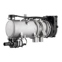
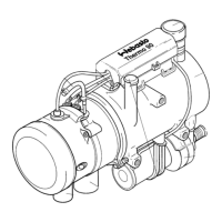
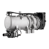
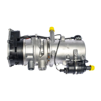
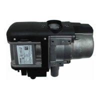
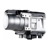
Thermo 90 S / Thermo 90 ST 7 Circuit diagrams
701
7 Circuit diagrams
7.1 General
The circuit diagrams (Figs. 701 to 704) show the possible
circuits for the Thermo 90 S heater with
– Standard clock
– Standard clock and separate circulating pump
control
– ADR and switch
– ADR and switch, without power take-off
The circuit diagrams (Figs. 705 to 708) show the possible
circuits for the Thermo 90 ST heater with
– Standard clock
– Standard clock and separate circulating pump
control
– ADR and switch
– ADR and switch, without power take-off

 Loading...


