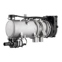
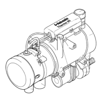
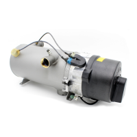
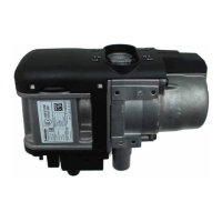
List of illustrations Thermo 90 S / Thermo 90 ST
IV
List of illustrations
301 Sequence of functions ............................................................................................................................... 302
501 General fault indications ............................................................................................................................ 501
502 Fault indications on fault lock-out............................................................................................................... 502
503 Visual check, burner back wall................................................................................................................... 503
504 Visual check, pilot flame outlet opening..................................................................................................... 504
505 Visual check, complete burner................................................................................................................... 504
701 System circuit for Thermo 90 S, 12 and 24 V, with standard clock............................................................ 702
702 System circuit for Thermo 90 S, 12 and 24 V, with standard clock and separate
circulating pump control............................................................................................................................. 703
703 System circuit for Thermo 90 S-ADR, 24 V, with switch............................................................................ 704
704 System circuit for Thermo 90 S-ADR, 24 V, with switch without power take-off........................................ 705
705 System circuit for Thermo 90 ST, 12 and 24 V, with standard digital timer ............................................... 706
706 System circuit for Thermo 90 ST, 12 and 24 V, with standard digital timer and separate
circulating pump control............................................................................................................................. 707
707 System circuit for Thermo 90 ST-ADR, 24 V, with switch.......................................................................... 708
708 System circuit for Thermo 90 ST-ADR, 24 V, with switch without power take-off...................................... 709
801 Specimen installations for heater in a truck ............................................................................................... 803
802 Fuel supply................................................................................................................................................. 804
803 Webasto fuel extractor............................................................................................................................... 805
804 Fuel extraction from the plastic tank (extraction through tank drain screw)............................................... 805
805 Fuel extraction from the plastic tank (extraction through tank fitting)......................................................... 805
806 Webasto fuel extractor............................................................................................................................... 806
807 Pipe/hose connection................................................................................................................................. 806
808 Metering pump, installation position and attachment ................................................................................ 807
809 Exhaust pipe opening, installation position................................................................................................ 808
901 Electrical connections (Thermo 90 S)........................................................................................................ 902
902 Changing the circulating pump .................................................................................................................. 903
903 Changing the temperature limiter and temperature sensor ....................................................................... 905
904 Changing the combustion air fan ............................................................................................................... 906
905 Changing the burner, flame monitor and glow plug ................................................................................... 908
906 Changing the burner head ......................................................................................................................... 909
 Loading...