Do you have a question about the weBoost drive 3G-M and is the answer not in the manual?
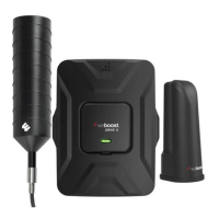
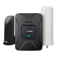
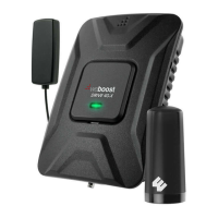
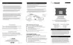
Details the components included in the weBoost Drive 3G-M Signal Booster kit.
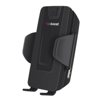
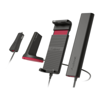
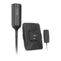
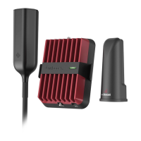
Lists and describes various optional antenna kits available for the signal booster.
Instructions for positioning and installing the external vehicle antenna.
Details how to route the outside antenna cable safely into the vehicle.
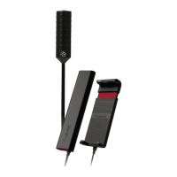
Guidance on mounting the inside antenna for optimal signal coverage.
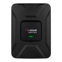
Steps for connecting the signal booster to antennas and power.
Indicates the booster is powered and operating at maximum gain.
Signifies the booster has shut off to prevent oscillation or feedback.
Shows the booster operating at reduced gain to prevent oscillation.
Provides steps to resolve red light indicators on the signal booster.
Steps to diagnose issues when the signal booster lights are off.
Explains how weather impacts antenna performance.
Clarifies 800 MHz and 1900 MHz bands for cell phones.
Warns against direct cell phone connection using adapters.
Advises connecting power after antennas are attached.
Specifies minimum separation for inside antennas from users.
Mandates antenna placement at least 8 inches from any person.
Confirms required power supply specifications.
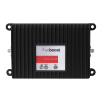
Identifies the specific model number of the signal booster.
Lists the types of connectors used on the signal booster.
Specifies the antenna impedance compatibility for the device.
Indicates the operating frequency bands of the signal booster.
Details the nominal gain across frequency bands.
Specifies the bandwidth for 20 dB signal gain.
Shows the power output for a single cell phone connection.
Details uplink power output for multiple channels.
Details downlink power output for multiple channels.
Specifies the typical noise figure for downlink and uplink.
Indicates the isolation level between components.
Lists the electrical power requirements for the signal booster.
| Product Type | Cellular Signal Booster |
|---|---|
| Frequency Bands | 800 MHz, 1900 MHz |
| Max Gain | 50 dB |
| Gain | Up to 50 dB |
| Power Supply | 12V DC |
| Connector | SMA |
| Frequency | 824-894 MHz, 1850-1990 MHz |
| Coverage Area | Up to 1, 500 sq ft |
| Uplink | 824-849 MHz, 1850-1910 MHz |
| Downlink | 869-894 MHz |
| Compatible Carriers | All major US carriers |