7
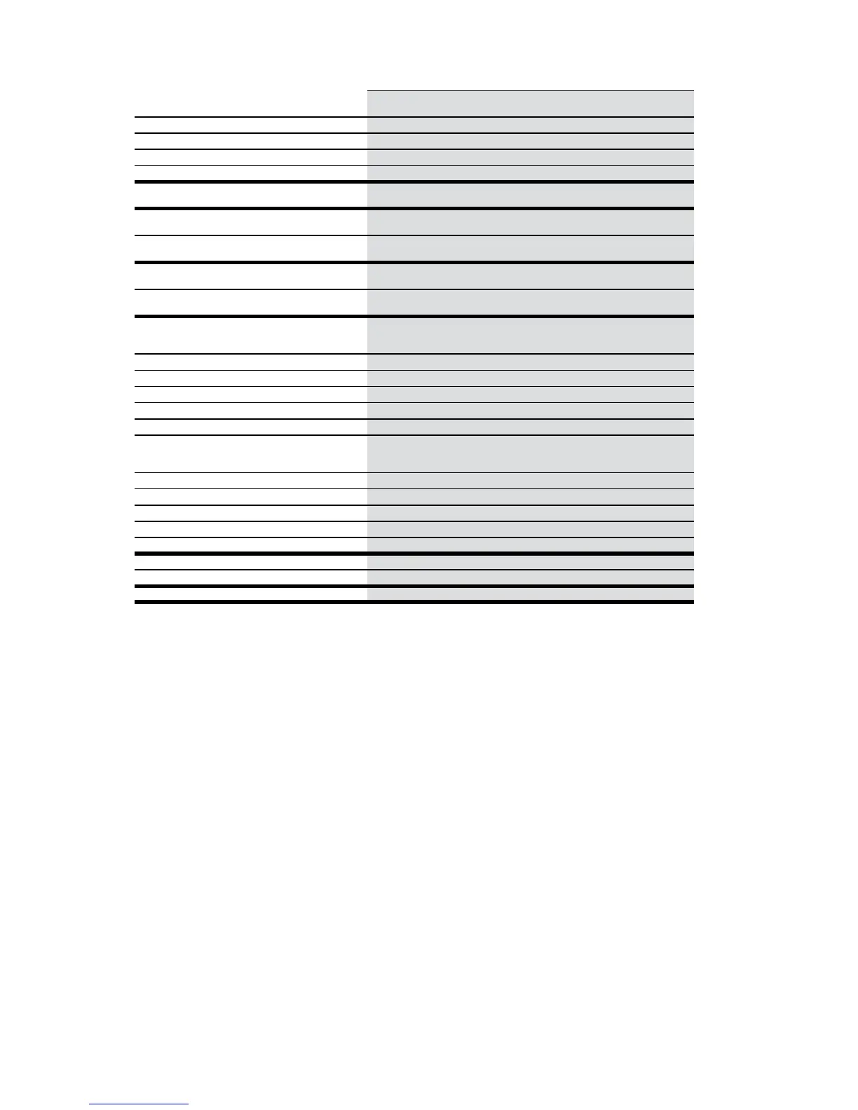
Signal Booster Specifications
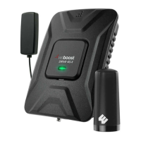
Drive 3G-M
Model Number 470002
Connectors SMA
Antenna Impedance 50 Ohms
Frequency 824-894 MHz / 1850-1990 MHz
Passband Gain (nominal)
800 MHz
47
.8
1900 MHz
43.8
20 dB Bandwidth (MHz)
800 MHz 1900 MHz
Typical
Maximum
41.1
42
.9
76
.1
76
.5
Power output for single cell phone (dBm)
800 MHz 1900 MHz
Uplink
Downlink
23.4
-3
.1
23
.4
-0
.9
Power output for multiple received channels
(Uplink) dBm
No. Tones
800 MHz 1900 MHz
2 23
.3 18.0
3 19
.8 14.5
4 17
.3 12.0
5 15
.3 10.1
6 13
.7 8.5
Power output for multiple received channels
(Downlink) dBm
No. Tones
800 MHz 1900 MHz
2 -1
.4 2.5
3 -4
.9 -1.0
4 -7
.9 -3.5
5 -9
.3 -5.4
6 -10
.9 -7.0
Noise Figure (typical downlink/uplink) 3 dB nominal
Isolation > 90 dB
Power Requirements 6 V, 0
.5 A
- 1
.5 A
(subject to uplink power)
The Manufacturer’s rated output power of this equipment is for single carrier operation
. For situations when multiple carrier signals are present, the rating
would
have to be reduced by 3
.5 dB, especially where the output signal is re-radiated and can cause interference to adjacent band users. This
power reduction
is to be by means of input power or gain reduction and not by an attenuator at the output of the device.