LX3 Series User Manual V2.0
Part 6 Module & Product specification
IN
OUT
PW R RU N
BA T
ER R
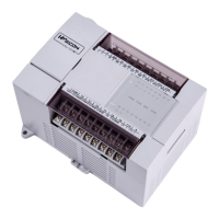
LX V M R3 - 24 1 6
① Mounting hole
② Input blocks
③ Output blocks
④ Output display
⑤ Input display
⑥ Power LED
Run LED
Error LED
⑦ DIN pin installation joint
⑧ Cover
⑨ Programming Port COM1(Standard)
⑩ RUN/ STOP
⑪ COM2 (Optional)
⑫ Socket for additional module
⑬ USB download port
⑭ Socket for BD module
⑮ Button battery (under the BD module)
Part 7 Communication Interface
The LX3V series PLC has two communication port, support RS422 (standard) and RS485 (optional).
1
2
3
4 5
6
7
8
COM1
programming port
(Rs422 and RS485 in this
port can t be used at the ’
same time)
Transmitted data (negative)
Transmitted data (positive)
COM1/COM2
(RS 485 optional)
 Loading...