7
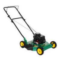
UPPER CHUTE (See Fig. 6A and 6B)
1. Lower mower to its lowest cutting position.
2. Assemble upper chute by inserting curved end into
hole in back of cover.
NOTE: Handle carefully so as not to damage full bag
in di ca tor.
Fig. 6A
3. Push in upper chute until it is in line with lower chute
and slide together.
4. Secure with rubber latch by hooking hole in latch over
latch pin.
Fig. 6B
FULL BAG
INDICATOR
LOWER
CHUTE
LATCH
PIN
RUBBER
LATCH
UPPER
CHUTE
COVER
ASSEMBLY
5
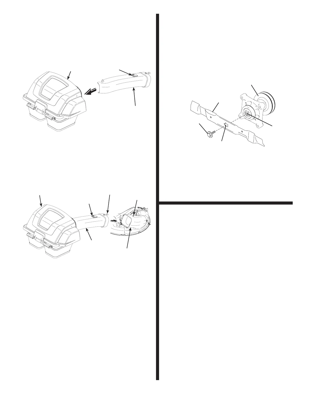
BLADE REMOVAL/REPLACEMENT
(See Fig. 7)
1. Raise mower to highest position to allow access to
blade.
NOTE: Protect your hands with gloves and/or wrap blade
with heavy cloth.
2. Remove blade bolt by turning coun ter clock wise.
3. Install new blade with stamped "GRASS SIDE" facing
downward.
6
IMPORTANT: To ensure proper as sem bly, center hole in
blade must align with star on mandrel assembly.
4. Install and tighten blade bolt securely (45-55 Ft. Lbs.).
IMPORTANT: Special blade bolt is heat treated.
BLADE
BLADE BOLT
(SPECIAL)
CENTER HOLE
STAR
MANDREL ASSEMBLY
Fig. 7
LEVEL MOWER DECK
Ensure deck is properly leveled for best mower per for mance.
See your riding mower manual for instructions.
7
UPPER
CHUTE
COVER
ASSEMBLY
FULL BAG
INDICATOR