Do you have a question about the Weider 8300 Hard Drive and is the answer not in the manual?
Read and follow all safety instructions before using the hard drive system.
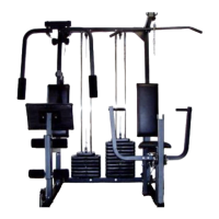
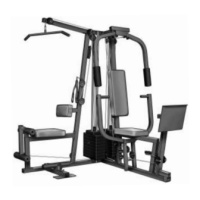
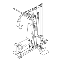
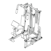
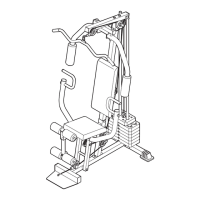
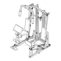
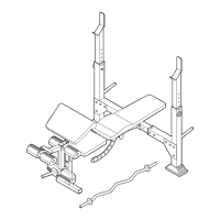
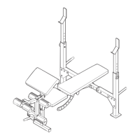
Introduction to the WEIDER 8300 system and its main parts.
Step 1 & 2: Attaching the stabilizer and base components.
Step 2: Securing the weight upright and installing rollers.
Step 3 & 4: Attaching side guard brackets and loading weights.
Step 5: Securing the side guards to the VKR side guard.
Step 6: Attaching side guards using self-tapping screws.
Step 7: Connecting front upright to base and weight upright.
Step 8: Assembling rear upright, top, and U-bracket.
Step 9 & 10: Installing side guard L-brackets and weight cable.
Step 11 & 12: Attaching VKR upright and stepper tube.
Step 13: Connecting left and right VKR arms.
Step 14 & 15: Attaching armrests and handles to VKR arms.
Step 16 & 17: Mounting small backrest and installing press arm.
Step 18 & 19: Installing press arm handles and short arm shocks.
Step 20 & 21: Connecting arm shocks and backrest brackets.
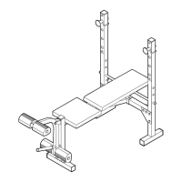
Step 22 & 23: Attaching backrest brackets and press seat.
Step 24 & 25: Connecting leg lever and installing pad tubes.
Step 26 & 27: Attaching side guard and butterfly seat.
Step 28: Installing left and right butterfly arms.
Step 29 & 30: Attaching arm brackets and long arm shocks.
Step 31 & 32: Connecting long arm shocks and installing grips.
Step 33 & 34: Applying decals and performing final cable checks.
How to change the weight setting using the weight pin.
Procedure for adjusting the press backrest to three positions.
Instructions for attaching and detaching the press seat.
Connecting the leg lever to the low pulley station.
Connecting the lat bar or nylon strap to the high pulley station.
Connecting the lat bar or nylon strap to the low pulley station.
Instructions for tightening slack cables to ensure proper resistance.
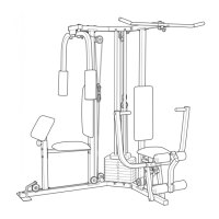
Diagram illustrating the correct routing of pulley and weight cables.
| Type | Home Gym |
|---|---|
| Brand | Weider |
| Stations | 6 |
| Weight Capacity | 300 lbs |
| Model | 8300 Hard Drive |