8 5
1. Before assembling this product, make sure that
you understand the information in the box
above.
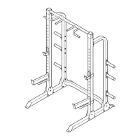
Turn one of the Stabilisers (2) so the warning decal
is facing up as shown. Note that on one side of the
Stabiliser there is an indentation around each of the
two holes. Insert two M10 x 72mm Carriage Bolts
(21) through the holes in the Stabiliser so that the
bolt heads fit into the indentations.
Slide the bracket on the Main Frame (1) onto the
two M10 x 72mm Carriage Bolts (21) in the
Stabiliser (2). Make sure that the Main Frame is
turned as shown. Tighten an M10 Nylon Locknut
(18) onto each Carriage Bolt.
Press a 60mm Round Endcap (10) onto each end of
the Stabiliser (2).
1
Before beginning assembly, carefully read the
following information and instructions. If assis-
tance is needed, call
0345-089009.
¥ Assembly requires two people.
¥ Place all parts in a cleared area and remove the
packing materials. Do not dispose of the packing
materials until assembly is completed.
¥ Tighten all parts as you assemble them, unless
instructed to do otherwise.
¥ To identify small parts, use the PART IDENTIFI-
CATION CHART in the centre of this manual.
¥ As you assemble the weight bench, make sure all
parts are oriented as shown in the drawings.
The following tools (not included) are required
for assembly:
¥ Two (2) adjustable wrenches
¥ One (1) rubber mallet
¥ One (1) standard screwdriver
¥ One (1) phillips screwdriver
¥ Lubricant, such as grease or petroleum jelly,
and soapy water.
Assembly will be more convenient if you have a
socket set, a set of open-end or closed-end
wrenches, or a set of ratchet wrenches.
Assembly
1
10
10
18
21
Decal
2
9
10
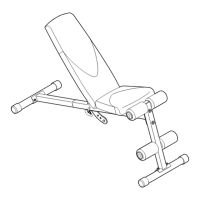
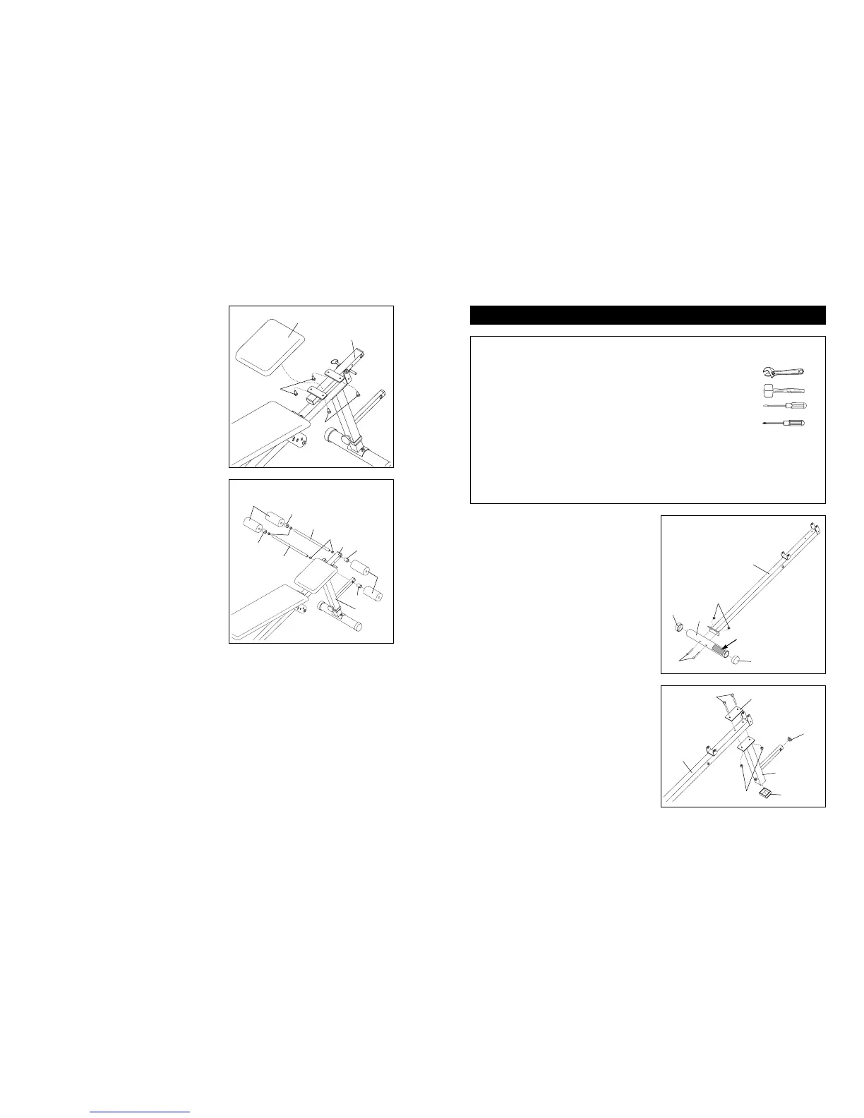
9. Attach the Seat (9) to the brackets on the Seat
Frame (5) with four M6 x 16mm Screws (15).
10. Press 19mm Round Inner Caps (13) into the ends
of the Long Pad Tube (12) and the Short Pad Tube
(31).
Slide a Plastic Spacer (3) and a Foam Pad (11)
onto one end of the Long Pad Tube (12). Insert the
Long Pad Tube into the hole in the Seat Frame (5).
Slide a Plastic Spacer (3) and a Foam Pad (11)
onto the other end of the Long Pad Tube.
Mount the Short Pad Tube (31) in the Leg (6) by
following the instructions above.
11. Make sure that all parts are tightened before
you use the weight bench. Cover the floor
beneath the weight bench to protect the floor.
5
9
31
3
6
11
11
3
3
3
5
13
12
13
15
15
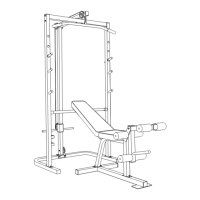
2. Insert two M10 x 70mm Bolts (19) through the holes
in the Support Plate (27) and then through the indi-
cated holes in the Main Frame (1).
Slide the bracket on the Leg (6) onto the two M10 x
70mm Bolts (19). Tighten two M10 Nylon Locknuts
(18) onto the Bolts.
Press a Square Bushing (22) onto the lower end of
the Leg (6). Press a 25mm Square Inner Cap (24)
into the tube on the Leg.
19
1
6
18
24
22
27
2
 Loading...