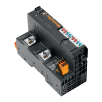
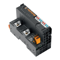
The Weidmüller u-control UC20 series comprises programmable logic controllers designed for industrial automation applications. These controllers, including the UC20-WL2000-AC, UC20-WL2000-AC-CAN, and UC20-WL2000-IOT models, serve as head stations for executing control programs and integrating into existing network architectures or HMIs.
Function Description
The UC20 controllers manage u-remote I/O modules, communicating via the u-remote system bus. Up to 64 active u-remote I/O modules can be connected to a single controller. The controllers are configured, parameterized, and programmed using an integrated web application, u-create web, accessible via a web browser or, for u-OS, through installed apps like CODESYS or Node-RED. The UC20-WL2000-AC and UC20-WL2000-IOT controllers support u-create web for programming according to IEC 61131-3 and JavaScript through Node-RED. The UC20-WL2000-AC and UC20-WL2000-AC-CAN models can be configured with the u-OS operating system. The UC20-WL2000-AC-CAN model also features a CAN interface for use with u-OS.
The main power supply for the station is integrated into the controller, with power supplied via two 4-pole connectors, separated into input and output current paths. The controllers utilize three internal current paths:
- Isys (System Current Path): Supplies the communication part of the I/O modules, fed from the controller input supply, and cannot be interrupted. It supports up to 64 active modules without power refresh.
- Iin (Input Current Path): Supplies the input circuit of input modules and connected sensors. This path requires refreshing with UR20-PF-I power-feed modules, which isolate the input current path to the left and start a new electricity segment to the right.
- Iout (Output Current Path): Supplies the output circuit of output modules and connected actuators. This path requires refreshing with UR20-PF-O power-feed modules, which isolate the output current path to the left and start a new electricity segment to the right.
Important Technical Specifications
The UC20 series controllers conform to IP20 degree of protection (IEC 60529) and Flammability Rating UL 94 V-0.
- Connection: "PUSH IN" technology for solid and fine-wired conductors (0.14 to 1.5 mm², AWG 16-26). Two RJ-45 Ethernet connections are standard. The UC20-WL2000-AC-CAN model includes an additional CAN interface.
- Number of Modules: Max. 64 active u-remote I/O modules.
- Processor: Dual Core ARM A9, 624 MHz.
- Memory: 512 MB RAM, 8 GB flash, 128 KB NV-RAM (retain memory).
- Memory Card: microSD (max. 32 GB, NTFS not supported) can be inserted. For UC20-SL2000, it's needed for firmware installation. For UC20-WL2000, it allows Node-RED access.
- Battery: Lithium button cell CR1220 (not included), supplies the integrated real-time clock during power interruptions.
- Supply Voltage: 24 V DC +20%/-15% for system, inputs, and outputs.
- Max. Feed-in Current: 5 A for input and output modules.
- Current Consumption (Isys): < 116 mA.
- Dimensions (H x W x D): 120.0 mm / 4.72" (with release lever: 128.0 mm / 5.04") x 52.0 mm / 2.05" x 76.0 mm / 2.99".
- Weight: 223 g.
- Temperature Range:
- Operation (horizontal): -20°C to +55°C (2x5 A power supply).
- Operation (vertical): -20°C to +50°C (2x5 A power supply).
- Storage/Transport: -40°C to +85°C.
- Humidity: 95%, non-condensing (IEC 61131-2).
- Air Pressure: ≥ 795 hPa (altitude ≤ 2000 m) for operations, ≥ 700 hPa (altitude ≤ 3000 m) for storage/transport (IEC 61131-2).
- Vibration Resistance (IEC 60068-2-6): 3.5 mm amplitude (5-8.4 Hz), 1 g acceleration (8.4-150 Hz).
- Shock Resistance (IEC 60068-2-27): 15g over 11ms, half sine wave.
- Potential Isolation: Max. 28.8 V inside a channel, 500 V DC field/system (EN 60079-15:2010).
- Pollution Degree: 2 (DIN EN 60664-1:2008).
- Overvoltage Category: II (DIN EN 50178).
Usage Features
- Installation: Modules are installed on a DIN rail (35 x 7.5 mm or 35 x 15 mm) using a "double-click" mechanism for secure mechanical and electrical connection. Horizontal installation is typical, but vertical mounting is possible with reduced heat dissipation and specific end bracket requirements.
- Wiring: "PUSH IN" connectors allow for easy insertion of fine-wired conductors. Color-coded pushers indicate connections (White: Signal DC/AC, Blue: GND, Red: 24 V DC, Green: Functional Earth (FE), Black: Signal AC).
- Earthing and Shielding: Controllers and modules are electrically connected to the DIN rail via an FE spring. Proper earthing of the DIN rail to protective earth (PE) is crucial for EMC. Shielded cables are recommended to combat interference, with proper connection to earth potential over a large surface area.
- Power Supply Calculation: Individual calculation of current demand for each station installation is required, considering system, input, and output current paths. Power-feed modules (PF-I and PF-O) are used to refresh current paths when demand exceeds 5 A (input) or 10 A (output).
- Firmware Management: Firmware updates and downgrades are performed via u-create web or u-OS. Downgrades may lead to data incompatibility, so saving configurations is recommended.
- Reset Functions: Controllers can be reset to default settings with or without a password. This clears application data, network settings, and user accounts but does not affect data on a mounted SD card or licenses in recovery mode.
Maintenance Features
- Component Replacement: Plug-in units, connectors, cables, batteries, and microSD cards can be replaced.
- Plug-in Unit: Swivels 90° for removal.
- Connectors: Can be slid off the frame after pressing both sides.
- Cables: Removed by pushing in the pusher with a 3-mm screwdriver.
- Battery: Replaced using tweezers or a screwdriver, ensuring proper disposal.
- microSD Card: Unlocked by briefly pressing on it, then removed and replaced.
- Troubleshooting: LED indicators (PWR, SF, BF, MT, RUN/STOP, L/A X1, L/A X2, and power supply LEDs 3.1, 3.2, 3.4, 4.1, 4.2, 4.4) provide status information and aid in diagnosing issues. Recommended actions for malfunctions include checking supply voltage, module connections, Ethernet cables, and replacing the controller if internal fuse defects are indicated.
- Insulation Test: Must be performed before each commissioning according to national regulations. Test voltage within a channel (24 V to GND) must not exceed 28.8 V. Max. 500 V can be applied to other connection points.
- Disassembly and Disposal: Products are subject to WEEE directive for collection and recycling. Batteries and sensitive data on microSD cards must be disposed of correctly. Weidmüller offers disposal services for end-of-life products.