Do you have a question about the Weidmüller UC20-WL2000-AC and is the answer not in the manual?
Explains safety symbols and notes used in the documentation.
Lists related manuals and resources for comprehensive information.
Provides general safety instructions for handling u-control products.
Defines the intended applications and usage conditions for u-control products.
Details safety requirements for operating in potentially explosive environments.
Covers CE compliance, directives, and software licensing terms.
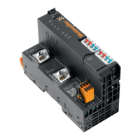
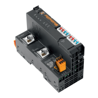
Provides a detailed description of the controller's components and interfaces.
Lists key technical specifications such as dimensions, protection class, and approvals.
Describes the compatibility and connection of u-remote I/O modules.
Details the PG 1.5 mm connector and its conductor connections.
Explains the mounting and fixing elements for the u-control station.
Describes the information provided on the controller's type plate.
Mentions the controller's battery for real-time clock backup.
Discusses the use of an SD card for firmware and data storage.
Outlines the sequence and restrictions for arranging modules in a u-control station.
Describes the horizontal and vertical installation orientations for the u-control station.
Specifies minimum distances required for installation and ventilation.
Details requirements for operation in potentially explosive atmospheres (Zone 2).
Explains the "PUSH IN" connection system and recommended wire-end ferrules.
Covers internal current paths, demand calculation, and power supply considerations.
Provides an example calculation for determining power supply requirements.
Explains how to calculate power loss in controllers and modules.
Discusses feedback energy in digital output modules and prevention methods.
Details the UC20-WL2000-AC controller, its features, and status indicators.
Details the UC20-WL2000-IOT controller, its features, and status indicators.
Details the UC20-SL2000-EC controller, its features, and status indicators.
Details the UC20-SL2000-EC-CAN controller, its features, and status indicators.
Covers general preparations, environmental conditions, and DIN rail mounting.
Provides step-by-step instructions for assembling the u-control station on a DIN rail.
Details wiring procedures, including recommended ferrules and tools.
Instructions for inserting the battery into the controller.
Instructions for inserting the SD card into the controller.
Outlines procedures for performing insulation tests before commissioning.
Explains the principles of earthing shielded cables for interference resistance.
Discusses potential-free and non-isolated designs and their implications.
Covers EMC requirements and principles for ensuring compatibility.
Details best practices for shielding cables to prevent interference.
Lists prerequisites for commissioning controllers via u-create web.
Guides on how to access and launch the u-create web interface.
Explains how to access the built-in online help for u-create web.
Provides instructions for downloading and updating the controller firmware.
Details the process for resetting the controller to its factory default settings.
Explains how to reset the controller without a password using physical access.
Lists prerequisites for commissioning controllers using u-create studio.
Guides on creating and loading firmware onto the controller via SD card.
Describes how to use the DevAdmin web application for controller management.
Step-by-step instructions for removing and replacing the plug-in unit.
Detailed guide on how to remove and replace connectors.
Instructions for removing and replacing cables connected to the modules.
Procedures for replacing the controller's battery.
Instructions for replacing the controller's SD card.
Step-by-step guide to disassembling the u-remote station.
Provides guidance on the proper disposal of u-control products according to WEEE.
Lists LED status and recommended actions for the UC20-WL2000-AC controller.
Lists LED status and recommended actions for the UC20-WL2000-IOT controller.
Lists LED status and recommended actions for UC20-SL2000-EC/EC-CAN controllers.
Lists various accessories available for the u-control system.
Provides a list of replacement parts for specific controllers.
Explains coding elements for module placement and orientation.
Details the structure and meaning of serial numbers.
Information on contacting support and service representatives.
| Product type | Controller |
|---|---|
| Number of digital inputs | 4 |
| Number of digital outputs | 4 |
| Number of analog inputs | 2 |
| Number of analog outputs | 2 |
| Protection class | IP20 |
| Output Voltage | 24 V DC |
| Mounting method | DIN rail |
| Communication interface | Ethernet |
| Input Voltage | 100-240 V AC |
| Input Frequency | 50/60 Hz |
| Operating Temperature | -20°C to +60°C |
| Storage Temperature | -40°C to +85°C |