Do you have a question about the Weidmüller UC20-SL2000-EC-CAN and is the answer not in the manual?
Explains safety symbols, notes, and warnings used in the manual.
Lists related manuals and resources for comprehensive understanding.
Details the specific hardware versions of controllers covered in this manual.
Provides essential safety instructions for handling u-control products.
Defines the specific applications and operational scope of the UC20 series products.
Outlines safety requirements for operating in potentially explosive environments.
Contains compliance information, certifications, and legal disclaimers.
Describes the UC20 controller's main features, components, and ports.
Lists key technical specifications, environmental data, and approvals.
Details compatible u-remote I/O modules and their specifications.
Explains the specifications and use of the PG 1.5 mm connector.
Describes the methods for mechanically mounting the station components.
Covers type plates, batteries, and memory cards for controller identification.
Guides on the correct sequence and placement of modules in the station.
Details how to orient the u-control station during installation (horizontal/vertical).
Specifies minimum distances required for installation and ventilation.
Addresses specific configuration requirements for explosive environments.
Explains the "PUSH IN" connection technology for cabling.
Details current requirements and power supply considerations.
Provides an example for calculating power supply needs and current demand.
Explains how to calculate power loss in the controller and station.
Discusses feedback energy management in digital output modules.
Detailed description of the UC20-WL2000-AC controller, including status indicators.
Detailed description of the UC20-WL2000-IOT controller, including status indicators.
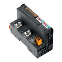
Detailed description of the UC20-SL2000-EC controller, including status indicators.
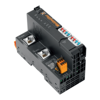
Detailed description of the UC20-SL2000-EC-CAN controller, including status indicators.
Covers initial steps, environmental conditions, and DIN rail preparation.
Step-by-step guide for physically assembling the station and modules.
Instructions for connecting cables to the station modules using recommended ferrules.
Procedure for correctly inserting the controller's battery.
Procedure for correctly inserting the controller's SD card.
Explains the insulation testing procedure required before commissioning.
Discusses proper methods for earthing shielded cables to prevent interference.
Explains the electrical potential relationships within the station for safe operation.
Details measures to ensure electromagnetic compatibility and reduce interference.
Covers techniques and best practices for shielding cables against interference.
Lists prerequisites for commissioning via the u-create web interface.
Guide on how to launch and access the u-create web interface.
Instructions for using the built-in online help for u-create.
Steps for downloading and installing controller firmware via u-create web.
Procedures for resetting the controller to factory defaults with or without password.
Lists prerequisites for commissioning via the u-create studio software.
Guide on firmware installation for UC20-SL2000 series using u-create studio.
Explains how to access and use the DevAdmin tool for configuration and diagnostics.
Procedure for safely removing and replacing the controller's plug-in unit.
Steps for safely removing and replacing connectors on modules.
Instructions for safely removing and replacing cables connected to modules.
Procedure for safely replacing the controller's battery.
Procedure for safely replacing the controller's SD card.
Guide on how to safely take apart the u-remote station and its modules.
Information on proper disposal of the equipment according to regulations.
Details LED status and troubleshooting steps for the UC20-WL2000-AC controller.
Details LED status and troubleshooting steps for the UC20-WL2000-IOT controller.
Details LED status and troubleshooting for SL-EC and SL-EC-CAN controllers.
Lists various accessories available for the u-control system.
Lists available replacement parts for the controllers.
Provides examples of coding for module placement and station configuration.
Explains the structure and meaning of the controller serial numbers.
Information on how to get support and contact responsible country representatives.
| Type | Controller |
|---|---|
| Model | UC20-SL2000-EC-CAN |
| Qty. | 1 |
| CAN | Yes |
| Input Voltage/Power Supply | 24 V DC |
| Protection Class | IP20 |
| Operating temperature | -25°C to +55°C |
| Communication Protocol/Interface | CAN |
| Operating Temperature Range | -25 °C ... 60 °C |