3 Systemoverview | General description of the controller
11Manual u-control2604080000/03/08.2020
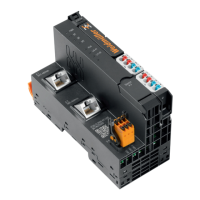
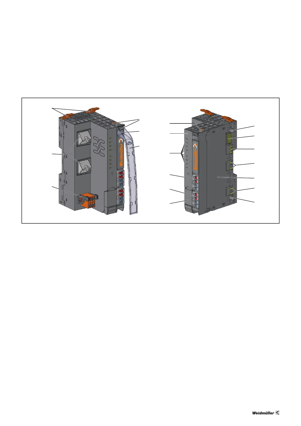
3.1 General description of the controller
1
2
4
5
6
12
10
11
9
8
7
14
13
13
15
16
18
17
3
Controller (example: UC20-SL2000-EC-CAN)
1 Release lever for the DIN rail fixing
2 Data line connection (RJ45)
3 CAN interface (only UC20-SL2000-EC-CAN)
4 Seats for module markers
5 Type designation
6 Swivel marker for labelling modules and channels (optional)
7 Connector frame unlocking device
8 LED power supply controller
9 Controller status LEDs
10 Power supply connector for the system and input modules
11 Power supply connector for output modules
12 Service flap (access USB port)
13 Latching hook for latching onto module sides
14 System bus
15 System current path
16 Input current path
17 Type plate
18 Output current path
 Loading...