3 Systemoverview
9Manual u-control2604080000/03/08.2020
3 System overview
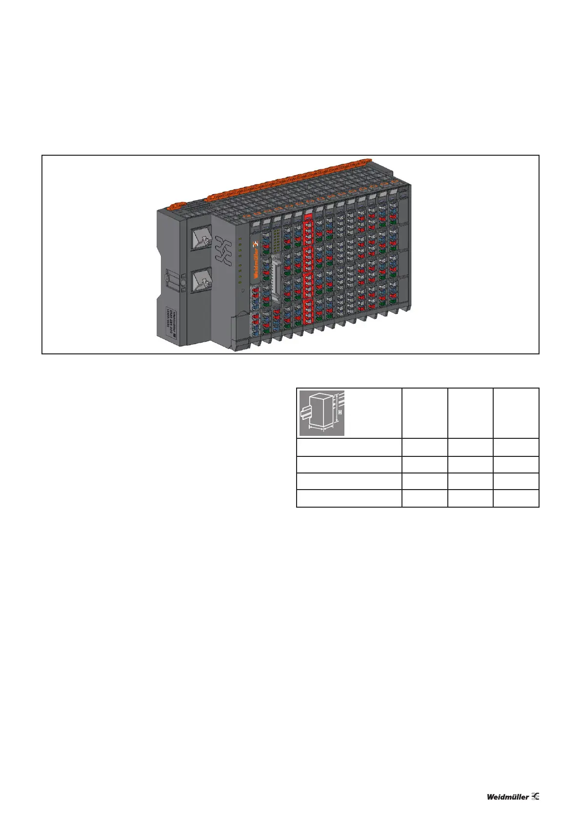
Example arrangement of a u-control station
The products of the u-control series are programmable logic
controllers. The UC20-WL2000 controllers are congured,
parameterised and programmed using the integrated en-
gineering tool u-create web via a web browser. The UC20-
SL2000 controllers are congured, parameterised and
programmed using the separate engineering tool u-create
studio.
Up to 64 active u-remote I/O modules can be connected to a
controller. The controller and the I/O module of a u-control-
station communicate over the u-remote-system bus.
The following components belong to a u-control-station:
– Controller: head station for production and execution of
control programs and for integration into the existing net-
work architecture or into HMIs
– Active I/O modules:
– Modules with digital input (DI) or digital output (DO)
with 4, 8 or 16 channels
– Modules with analogue input (AI) or analogue output
(AO) with up to 8 channels
– Safety-related supply terminals (PF-O-xDI-SIL) 24 V for
output current with either one or two dual channel
inputs for safety circuits
– Passive I/O modules (no fieldbus communication)
– 24-V power-feed modules (PF) for input or output cur-
rent
– Potential distribution modules (AUX)
– Empty modules acting as placeholders (ES)
– Mechanical fixing elements
– End brackets
– End plate
Height (H) Width (W) Depth (D)
Controller 120.0 / 4.72 52.0 / 2.05 76.0 / 2.99
I/O module 120.0 / 4.72 11.5 / 0.45
1)
76.0 / 2.99
End plate 120.0 / 4.72 3.5 / 0.14 76.0 / 2.99
End bracket 120.0 / 4.72 8.0 / 0.32 36.0 / 1.42
Dimensions of the u-control station components (mm / inch)
“Double-click” installation
The u-control station modules can be installed quickly and
simply. When attaching the module to the DIN rail, a clear
clicking noise can be heard, which means that the module
has clicked into place. In the second step, which involves
pushing the module being installed together with the neigh-
bouring module, a further clicking noise indicates that the
modules have been correctly connected to each other.
 Loading...