Part number 550-143-010/1021
12
GV90+ series
2
gas-fired water boiler – boiler manual
Install water piping
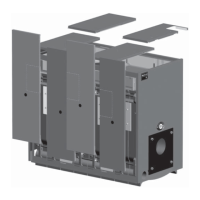
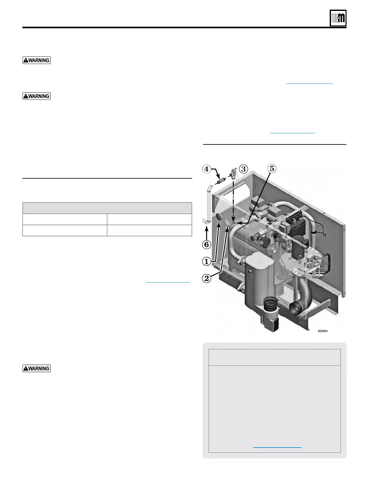
Legend
1 Jacket plug for unused relief valve jacket opening.
2 Jackets are provided with two relief valve open-
ings because each jacket size is used for two boiler
sizes. Cover the unused opening with the plug
provided.
3 Boiler relief valve (from accessory bag)
4 ¾” x 3” nipple, provided in accessory bag
5 ¾” relief valve tapping in back section
6 Connect minimum ¾” discharge piping to relief
valve.
See Figure 13, page 13.
Air separator
Install an air separator in the piping as shown in this
manual. For single-zone systems, install the air separator
in the return piping as shown in Figure14,page14. is
allows mounting the automatic air vent and expansion tank
o of the separator.
Install relief valve
1. Install relief valve ONLY as shown in Figure12.
2. Connect discharge piping to safe disposal location,
following guidelines in Figure13,page13.
Use two wrenches when tightening water piping at
boiler
, using one of the wrenches to prevent the boiler
interior piping from turning. Failure to support the boiler
piping connections to prevent them from turning could
cause damage to boiler components.
e cast iron heat exchanger return temperature must be
kept at or above 140°F during all times of operation to
prevent possibility of corrosion due to condensation. is
is done automatically, using the boiler's internal circula-
tors. DO NOT remove or tamper with these circulators.
Failure to comply could result in severe personal injury,
death or substantial property damage.
General piping information
Minimum pipe size for boiler loop piping
Figure 11 Provide boiler loop piping no smaller than listed
below (based on 20°F temperature rise)
Boiler loop pipe size, Minimum
GV90+ 3 or 4 1”
GV90+ 5 or 6 1¼”
Additional limit controls
Following standard industry practices, if installation is to comply with
ASME or Canadian requirements, an additional high temperature
limit
may be needed. Consult local requirements for other codes/
standards to determine if needed. Wire as shown in Figure67,page56 .
• Install a manual reset high temperature limit between the boiler
and the isolation valve.
• Wire the manual reset limit in series with the boiler limit control.
• Set the manual reset limit control at least 20°F above the boiler
limit control setting (maximum setting 220°F).
Low water cut-o
A low water cuto device is required when boiler is installed above
radiation level or by certain state or local codes or insurance compa-
nies. e boiler has a pre-installed water temperature/LWCO sensor.
If boiler is connected to heating coils located in air han-
dling units where they can be exposed to refrigerated
air, use ow control valves or other automatic means to
prevent gravity circulation during cooling cycle. Circu-
lation of cold water through the boiler could result in
damage to the heat exchanger, causing possible severe
personal injury, death or substantial property damage.
Backow preventer
Where required by codes, install a backow preventer in the cold
water ll line, as shown in suggested piping diagrams on following
pages. Install a check valve if a backow preventer is not installed.
Figure 12 Install pipe relief valve
 Loading...