Part number 550-143-010/1021
2
GV90+ series
2
gas-fired water boiler – boiler manual
1 Integrated boiler control
e Integrated Boiler Control (IBC) responds to signals from the room thermostat, air
pressure switch, inlet water sensor, boiler water temperature/LWCO sensor and boiler
limit circuit to operate the circulators, gas valve, igniter and blower. When a room ther-
mostat calls for heat, the IBC starts the system circulator and blower.
e IBC runs the blower to purge the boiler ue passages, then turns on the igniter and
lets it warm up.
Aer igniter warm-up, the IBC opens the gas valve, turns the igniter o, and checks for
ame. e ame must come on within 4 seconds or the IBC will shut down and try the
full cycle again.
When the room thermostat is satised, the IBC turns o the boiler components and
waits for the next heat call.
e IBC indicator lights show normal sequence when the lights are on steady. When a
problem occurs, the IBC ashes combinations of lights which indicate the most likely
reason for the problem.
While attempting to satisfy the heat demand, the control module monitors the boiler
temperature changes via the temperature/LWCO sensors and determines whether or not
the available hot water will satisfy the demand, only running the circulator. If additional
heat is needed, the sequence continues. When DHW (if used) calls for heat, sequence
above is bypassed.
2 Transformer
e control transformer reduces line voltage to 24 volts for the gas valve and limit circuit.
3 Blower
e blower pulls in air and mixes it with gas from the gas valve. e blower forces this
mixture into the burner for combustion inside the boiler chamber.
4 Recuperator
e recuperator is a stainless steel heat exchanger that increases boiler eciency by ex-
tracting additional heat from the ue gases. Return water passes through the recuperator
before entering the boiler.
5 Water temperature/LWCO sensor
e water temperature/LWCO sensor provides a signal to the control module
to turn o the gas valve if the temperature in the boiler goes above its setting.
(e circulator will continue to run as long as there is a call for heat.) e low
water cuto (LWCO) sensor will shut o the boiler when the water level drops
below sensor.
6 System circulator
e system circulator circulates water through the external (system) piping. e ow
rate of the circulator is controlled by the IBC, depending on the temperature of the water
entering the boiler sections. Pump must remain on boiler — do not remove.
7 Bypass circulator
e IBC operates the bypass circulator to mix hot water from the boiler outlet with
colder return water from the system as needed to prevent condensation of ue gases in
the cast iron heat exchanger.
When the water returning to the boiler is below 140°F, the IBC regulates the bypass cir-
culator and system circulator ow rates to raise the return water temperature up to 140°F
before it enters the cast iron sections. By balancing these ow rates, the IBC can protect
against condensation in the cast iron heat exchanger even if return water is as low as 60°F.
Pump must remain on boiler — do not remove.
8 Air pressure switch
e air pressure switch signals the IBC, telling the control whether air is moving through
the blower.
9 Return water temperature sensor
e water temperature sensor monitors the temperature of the water entering the boiler
sections. e sensor sends this information to the IBC. e IBC determines how much
to adjust the circulator ow rates to provide at least 140°F water to the cast iron heat
exchanger.
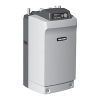
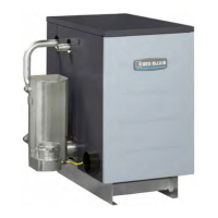
How it works . . .
LEGEND
a Supply to system, 1”NPT
b Return from system, 1”NPT
c Combustion air inlet tting —
3”PVC connection
d Flue outlet — 3”PVC connection
e Gas valve — negative pressure
regulated gas control
f Pressure/temperature gauge
g Flue way inspection port cover
h Sensor hose trap
i Manual air vent
j Relief valve
k ermal switch — a device that
shuts boiler o if ue tempera-
ture exceeds its setpoint
m Condensate trap — shipped
loose with boiler, eld installed
n On/o power switch
This boiler uses a negative-pressure-
regulated gas valve, set for an outlet
pressure approximately –0.20” water
column.
DO NOT set the outlet pressure higher
than factory setting.
 Loading...