EasyManua.ls Logo

Weil-McLain GV90+ User Manual

Weil-McLain GV90+
108 pages
To Next Page IconTo Next Page
Page #1 background imageLoading...
Page #1 background image
Part number 550-142-903/1016
®
Series 2
Gas-Fired Water Boilers
This manual must only be used by a qualified heating installer/service technician. BEFORE installing, read
all instructions in this manual and all other information shipped with the boiler. Perform steps in the order
given. Failure to comply could result in severe personal injury, death or substantial property damage.
Installation
Startup
Maintenance
Parts
Boiler Manual
Beginning Serial Number:
CP7538624

Table of Contents

Other manuals for Weil-McLain GV90+

Question and Answer IconNeed help?

Do you have a question about the Weil-McLain GV90+ and is the answer not in the manual?

Weil-McLain GV90+ Specifications

General IconGeneral
BrandWeil-McLain
ModelGV90+
CategoryBoiler
LanguageEnglish

Summary

Boiler Manual

How it works...

Hazard definitions

Please read before proceeding

Installer and User Warnings

Important safety warnings for installers and users regarding boiler operation and maintenance.

Prepare boiler location

High altitude installations

Guidelines for installing the boiler at higher altitudes, including component adjustments.

Service clearances

Recommended minimum clearances around the boiler for proper service access.

Check orifice plate — replace if necessary

Install condensate trap

GV90+ Suggested Condensate Pump Capacity

Table detailing recommended condensate pump capacities for GV90+ boilers.

Perform hydrostatic pressure test

Fill and connect water supply

Instructions for filling the boiler system and connecting the water supply for testing.

Drain and remove fittings

Procedure for draining the system and removing necessary fittings after testing.

Install water piping

Air separator

Information on installing an air separator in the piping system.

Install relief valve

Guidelines for correctly installing the relief valve.

Expansion tank

System water piping methods

Simplified pipe/circulator selection

Method for simplifying pipe and circulator sizing for residential applications.

Baseboard system piping — CIRCULATOR zoning (primary/secondary)

Baseboard system piping — ZONE VALVE zoning (direct connection)

Zone valve zoning — GV90+3, GV90+4 or GV90+5 (DO NOT apply to GV90+6)

Radiator system — zone-valve zoning

Radiator system — circulator zoning

Single-zone radiant heating or heat pump system

Adjust balancing valves

Instructions for manually adjusting supply water temperature using balancing valves.

Multi-zone radiant heating system

Outdoor reset

Application of outdoor reset control systems for supply water temperature regulation.

Piping snow melt systems or combination snow melt/space heating systems

Water chiller systems

Multiple boiler installations

Placing multiple boilers

Guidelines for locating and spacing multiple boilers in a boiler room.

Controlling multiple GV90+ boilers

Methods for controlling multiple GV90+ boilers using a boiler control/sequencing system.

Piping multiple GV90+ boilers

Recommendations for piping multiple GV90+ boilers in primary/secondary circuits.

Multiple boiler water piping

Easy-Fit® piping installation

Details on installing Easy-Fit® manifolds for multiple boiler water piping.

Piping schematic — typical for multiple GV90+ boilers, using Weil-McLain Easy-Fit manifolds

Piping layout — typical for multiple GV90+ boilers, using Weil-McLain Easy-Fit manifolds (2-boiler system)

Piping layout — typical for multiple GV90+ boilers, with DHW storage heaters (4-boiler system)

Piping layout — typical for multiple GV90+ boilers, using isolation exchanger

Venting & air — general

Common vent system removal and testing

Procedure for testing existing vent systems when replacing a boiler.

Vent and air termination options

DIRECT VENT installations

Instructions for direct vent installations, including air openings.

DIRECT EXHAUST installations

Instructions for direct exhaust installations, including air openings.

Manifolded combustion air option for DIRECT VENT multiple boiler installations

Air manifold sizing

Guidance on calculating the required cross-sectional area for combined air ducts.

GV90+ venting and air piping — OPTIONS and PIPING LIMITS

Vent and air piping materials

Commonwealth of Massachusetts installations

Vent termination requirements

DIRECT VENT — Boiler room air openings

Air openings

Required air opening sizes for direct vent installations with and without other appliances.

DIRECT VENT — Sidewall with W-M vent/air plate

Install Weil-McLain vent/air cap

DIRECT VENT — Sidewall with separate pipes

Multiple vent/air terminations

Guidelines for terminating vent and air connections for multiple boilers.

DIRECT VENT — Sidewall with 3” concentric

Install termination — concentric pipes

Instructions for installing concentric sidewall vent terminations.

DIRECT VENT — Vertical with separate pipes

Termination and fittings

Details on preparing and installing termination fittings for vertical venting.

DIRECT VENT — Vertical with 3” concentric

Mount concentric termination

Steps for mounting the concentric vent termination assembly at the roof penetration.

Concentric termination assembly (sidewall or vertical)

Vent and air piping and boiler connections

DIRECT EXHAUST & DIRECT VENT

Connecting vent and air piping for direct exhaust and direct vent systems.

DIRECT EXHAUST — Boiler room air openings

Special considerations for air openings

Details on tight construction, exhaust fans, and motorized dampers affecting air openings.

DIRECT EXHAUST — Sidewall

Termination and termination options

Options for sidewall termination of direct exhaust vent piping.

DIRECT EXHAUST — Vertical

Gas piping

Connecting gas supply piping

Procedures for connecting the gas supply piping to the boiler.

Wiring

Wiring connections

Diagrams and instructions for making power and thermostat wiring connections.

Additional limit controls

Guidance on wiring additional limit controls if used.

Thermostat(s)

Instructions for installing and wiring thermostats.

Field wiring connections — service switch and thermostat (or end switch) provided by installer

DHW, R & C Connections, Wiring multiple zones, Carbon monoxide detector

Wiring for DHW, R&C connections, multiple zones, and CO detectors.

Ladder wiring diagram

SCHEMATIC WIRING DIAGRAM

Start-up

Freeze protection guidelines

Guidelines to prevent personal injury or damage when using freeze protection fluids.

Clean system to remove sediment

Procedure for flushing the system to remove sediment before filling.

Water chemistry

Requirements for maintaining proper water chemistry in the boiler system.

Antifreeze

Information on using antifreeze products approved for GV90+ boilers.

Check for gas leaks

Verify gas/air orifice plate

Check thermostat circuit(s)

Inspect/fill condensate system

Final checks before starting boiler

Adjust boiler control settings

BOILER OPERATING TEMPERATURE

Setting the boiler operating temperature using the control knob.

BOILER ECONOMY SETTING

Adjusting the economy setting for time delay to save energy.

IMPORTANT

If boiler does not start correctly

Gas valve adjustment — altitude over 5,500 feet ONLY

Connect and adjust manometer

Procedure for connecting a manometer to adjust gas valve outlet pressure at high altitudes.

Final checklist

Department of Energy – Compliance

Integrated boiler control (IBC) sequence of operation — status light indications

Operating instructions

Annual start-up and general maintenance schedule

Service technician

Tasks to be performed by a qualified service technician during annual start-up.

Owner maintenance

Maintenance tasks for the owner to perform annually.

General maintenance tasks

Routine checks including boiler area, piping, and controls.

Annual start-up

Annual start-up only by qualified service technician

Emphasizes annual inspection and start-up by a qualified technician.

Routine inspections and checks

Detailed inspection procedures for boiler components and systems.

Inspect expansion tank

Inspect air openings

Verify combustion and ventilation air openings are unobstructed.

Inspect vent system and air piping

Visually inspect flue gas venting and combustion air piping for issues.

Inspect boiler heating surfaces

Inspect igniter

Inspect temperature mixing system

Inspect boiler relief valve

To complete Annual Start-up, perform startup and checks:

Cleaning boiler heating surfaces

To the blower assembly

Procedure for removing the blower housing for cleaning.

To clean heating surfaces

Steps for cleaning boiler heating surfaces using water spray.

Removing/cleaning/re-installing the recuperator

Re-install the recuperator

Troubleshooting

Before troubleshooting steps

Preparation steps and tools needed before starting troubleshooting.

Igniter

Gas Valve

Return temperature sensor

Supply Temperature sensor

IBC (Integrated Boiler Control)

IBC indicator lights — lockout modes

Explanation of IBC indicator lights indicating lockout conditions.

IBC indicator lights — non-lockout modes

Explanation of IBC indicator lights indicating non-lockout operating modes.

IBC harness plug receptacle and indicator light locations

Common causes and possible corrections, part 1

Common causes and possible corrections, part 2

CHART 1 Troubleshooting POWER light status

CHART 2 TSTAT/CIRC & POWER lights flashing

CHART 3 PRESS SWITCH & POWER lights flashing

CHART 4 FLAME & POWER lights flashing

CHART 5 TSTAT/CIRC light flashing and POWER light on steady

CHART 6 LIMIT light flashing and POWER light on steady

CHART 7 Insufficient heat or no heat to system (POWER light on steady)

CHART 8 Troubleshooting Sensor Ground and POWER light Solid and/or “LCO” shown on display

Replacement parts

Installation and service certificate

Certificate to be completed upon installation for record-keeping.

Section assembly

Jacket assembly

Blower assembly

Trim assembly

Interior panel

Dimensions and ratings

Dimension drawing

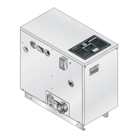
Diagram illustrating the physical dimensions of the boiler.

Boiler ratings

Multiple GV90+ boilers — ratings and engineering data

Engineering data — see page 103 for additional technical information

Handling ceramic fiber and fiberglass materials

NOTES

Related product manuals