EasyManua.ls Logo

Weil-McLain GOLD CGa-7 User Manual

Weil-McLain GOLD CGa-7
68 pages
To Next Page IconTo Next Page
Page #1 background imageLoading...
Page #1 background image
Part No. 550-101-009/0107
This manual must only be used by a qualified heating installer/service technician. Before installing, read all
instructions, including this manual, the burner manual and any related supplements. Perform steps in the order
given. Failure to comply could result in severe personal injury, death or substantial property damage.
GOLD CGa
s)NSTALLATION
s3TARTUP
Boiler Manual
s-AINTENANCE
s0ARTS
Gas-Fired Water Boilers
®
Question and Answer IconNeed help?

Do you have a question about the Weil-McLain GOLD CGa-7 and is the answer not in the manual?

Weil-McLain GOLD CGa-7 Specifications

General IconGeneral
BrandWeil-McLain
ModelGOLD CGa-7
CategoryBoiler
LanguageEnglish

Summary

Prepare Boiler Location

Codes and Checklist

Outlines codes and checks required before boiler location.

Clearances

Specifies required minimum clearances for boiler installation.

Vent System

Details requirements and inspection for the boiler's vent system.

Air Openings

Explains requirements for combustion and ventilation air openings.

Prepare Boiler: Placement and Setup

Boiler Placement and Setup

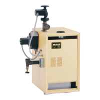
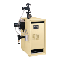
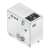
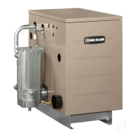
Guides on positioning and preparing the boiler for installation.

Inspect Orifices and Burners

Instructions on checking and verifying burner and orifice installation.

Prepare Boiler: Pressure Test

Hydrostatic Pressure Test

Details the procedure for conducting a hydrostatic pressure test.

Prepare Boiler: Draft Hood and Spill Switch

Prepare Boiler: Vent Damper Installation

Water Piping

General Piping Information

Provides overall guidelines for water piping installation.

Relief Valve

Explains proper installation and safety precautions for the relief valve.

System Water Piping

Guidelines for connecting the boiler to the overall system piping.

Water Piping: Single-Zone System

Water Piping: Multiple Zones

Piping: Low Temperature Systems

Gas Piping

Connect Gas Supply Piping to Boiler

Steps for connecting the gas supply to the boiler.

Natural Gas

Details gas piping requirements and specifications for natural gas.

Propane Gas

Details gas piping requirements and specifications for propane gas.

Field Wiring

Thermostat

Instructions for thermostat installation and wiring.

Start-up: Preparation

Check for Gas Leaks

Procedures for checking gas leaks before and during operation.

Fill the System with Water

Steps for filling the boiler and system with water and purging air.

Inspect System Water Piping

Instructions for checking water piping for leaks after filling.

Start-up: Operate Boiler

Starting the Boiler

Procedures for lighting and starting the boiler.

Check System and Boiler

Steps to verify system and boiler status after operation.

Start-up: If Boiler Doesn't Start

Troubleshooting steps when the boiler fails to start.

Start-up: Verify Operation

Check Burner Flames

How to inspect pilot and main burner flame quality.

Check-out Procedure Checklist

Boiler and System Checks

Checklist of initial checks before and during operation.

Test Ignition System Safety Device

Procedures for testing standing and spark-ignited pilot safety devices.

Operation: Standing Pilot Boilers

Lighting Instructions

Safety Precautions

Essential safety warnings and actions before lighting.

Lighting Instructions

Step-by-step guide for lighting the pilot and starting the boiler.

Turn Off Gas Procedure

Instructions on how to safely shut off gas to the appliance.

Operation: Spark-Ignited Pilot Boilers

Pilot Ignition

Process of igniting the pilot flame.

Troubleshooting Procedure

Before Troubleshooting

Lists necessary tools and initial checks before troubleshooting.

Troubleshooting: Vent Damper Failure

Troubleshooting: Standing Pilot Boilers

Chart 1: Standing Pilot – Boiler Will Not Fire

Diagnostic chart for a boiler that fails to fire.

Troubleshooting: Spark-Pilot Boilers

Control Indicator Lights – LOCKOUT Modes

Explains indicator lights related to lockout conditions.

Chart 2: Troubleshooting POWER Light Status

Diagnostic chart for POWER light status issues.

Chart 3: TSTAT CIRC & POWER Lights Flashing

Troubleshooting chart for TSTAT CIRC and POWER light flashing.

Chart 4: DAMPER Light Flashing

Troubleshooting chart for DAMPER light flashing issues.

Chart 5: FLAME & POWER Lights Flashing

Troubleshooting chart for FLAME and POWER light flashing.

Chart 6: FLAME light flashing and POWER light on steady

Troubleshooting chart for specific flame and power light conditions.

Chart 7: Insufficient heat or no heat (POWER light on steady)

Troubleshooting chart for lack of heat issues.

Replacement Parts: Controls

Control Module

Part number for the ignition control module.

Handling Ceramic Fiber and Fiberglass Materials

Related product manuals