Part number 550-142-903/1016
64
Final checklist
5SETHECHECKLISTFOLLOWINGTOENSUREBOILERIS
OPERATINGCORRECTLY
(AVETHEFOLLOWINGBEENCOMPLETED
❏
Is proper orifice plate installed? Refer to page 8 to check size
and fuel type.
Proper orifice plate must be used. Failure to do so
will cause severe personal injury, death or substan-
tial property damage.
❏
Thermostat heat anticipator (if available) set properly? Refer
to Field wiring, page 56.
❏
Read and followed all procedures and checks specified in the
Start-up section, beginning with page 59.
0ERFORMTHEFOLLOWING
❏
Inspect vent system for leaks. Verify vent (and air) piping are
functional and unobstructed.
❏
Measure natural gas input:
a. Operate boiler 10 minutes.
b. Turn off other appliances.
c. At natural gas meter, measure time (in seconds) required
to use one cubic foot of gas.
d. Calculate gas input:
3600 x 1000
number of seconds from step c
= Btuh
e. Btuh calculated should approximate input rating on
boiler rating label.
❏
Test temperature limit — While burners are operating, turn
Boiler Temp adjustment knob counterclockwise until display
reading is below actual boiler water temperature. Burners
should go off while circulator continues to operate. Turn
Boiler Temp adjustment knob clockwise until display read-
ing is above boiler water temperature and ignition sequence
should resume.
❏
Test additional field-installed controls — If boiler has an
additional low water cutoff, additional high limit or other
controls, test for operation as outlined by manufacturer.
Burner should be operating and should go off when controls
are tested. When controls are restored, boiler should restart.
❏
After placing the boiler in operation, the ignition system safety
shutoff device must be tested.
a. Connect voltmeter to gas valve terminals.
b. Turn off manual gas valve.
c. Set thermostat to call for heat.
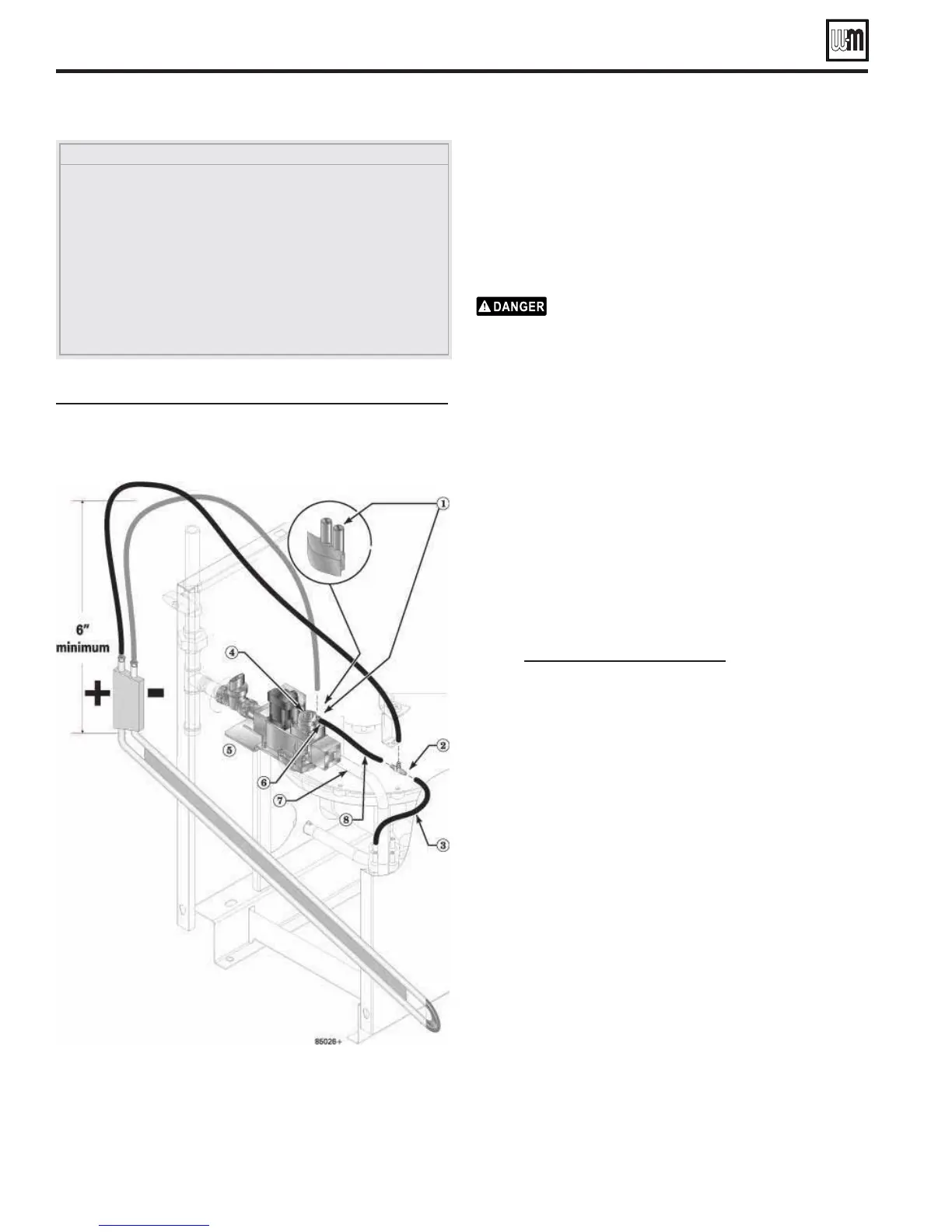
,EGENDFOR&IGURE
1 Gas control outlet pressure tap — located on back side of gas control. Use tap
closest to gas control gas outlet —Remove screw from gas control outlet pressure
tap and slide hose over tap
2 Add tee hose fitting as shown
3 Existing hose to gas control vent tap hose barb — Remove from gas control vent
tap and connect to end of tee as shown
4 Gas control pressure regulator cap
5 Honeywell Type VK8115V gas valve
6 Gas outlet vent tap
7 Gas outlet piping
8 Add hose from gas control vent tap to tee hose fitting
&IGURE Carefully connect manometer to gas valve as
shown, following instructions on this page
(see legend at above)
GV90+ Series 2 GAS-FIRED WATER BOILER — Boiler Manual
Start-up (continued)