Part number 550-142-903/1016
7
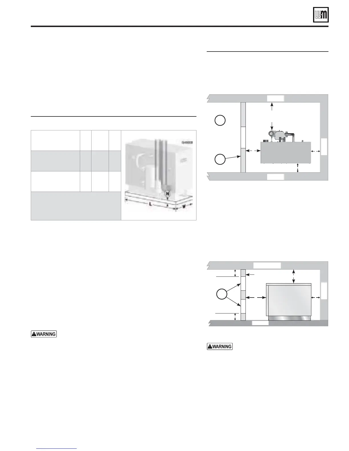
Foundation
Provide a solid brick or concrete foundation pad if any of the following
is possible:
s When the floor can become flooded.
s When the boiler mounting area is not level.
s When a high-profile condensate pump is used, provide a foundation
high enough that the GV90+ condensate connection is at least as high
as the condensate pump inlet connection.
&IGURE
Minimum foundation dimensions (inches)
"OILERMODEL 7 L (
GV90+3 / GV90+4 16 30¾ 2
GV90+5 / GV90+6 16 37¾ 2
* Increase height if needed to ensure
condensate trap outlet tee is above inlet
of condensate pump, when used.
Residential garage installation
Precautions
Take the following special precautions when installing the boiler in a
residential garage. If the boiler is located in a residential garage, per ANSI
Z223.1/NFPA 54, paragraph 5.1.9:
s Mount the boiler a minimum of
INCHESABOVETHEmOOR of the
garage to assure the burner and ignition devices will be no less than
18 inches above the floor.
s Locate or PROTECTTHEBOILER so it cannot be damaged by a moving
vehicle.
Minimum clearances
You can install GV90+ boilers in spaces smaller than Fig-
ure 2, page 6 recommended service clearances, but never
smaller than shown in Figure 4.
Installations with clearances less than shown in Fig-
ure 2, page 6 must have air openings sized and located as
shown in Figure 4.
s Always provide at least screwdriver clearance to jacket front panel screws
for removal of front panel for inspection and minor service.
s If the boiler
CANNOTBESERVICEDINPLACE, pipe the boiler with unions
and isolation valves so it can be slid out of the space and serviced in
an adjacent area.
s The space has to be equipped with a door so boiler can be accessed,
unpiped and removed.
Prepare boiler location (continued)
&IGURE Minimum clearances — when
clearances are less than recom-
mended service clearances of Fig-
ure 2, page 6, install as shown below:
Boiler
top
Front
10"
min
1"
min
1" min
4"
min
TOP VIEW
85006+c
Wall
Wall
Wall
A
B
! Area adjacent to access door must be accessible
and must allow for removal of the GV90+boiler
for service.
No other appliance or air mover (exhaust fan,
etc.) may be mounted in the same space.
" Access DOOR with fresh air openings
# Provide (2) Fresh air openings — Each with at
least 1 sq. inch per 1,000 Btuh of boiler input
Boiler
side
Front
1"
min
1"
min
4"
min
Access door
6" max
6" max
SIDE VIEW
Ceiling
Wall
Floor
85006+d
C
./4)#% 30%#)!, 2%15)2%-%.43
&/2!)2/0%.).'3
: For installations
with clearances less than recommended
service clearances (Figure 2, page 6), but
NOLESSTHANSHOWNIN&IGURE — An
access door must be provided, fitted with
two air openings as shown in Figure 4.
Each opening must have a free area no
less than 1 square inch per 1000 Btuh
input of the GV90+ boiler in the space.
$/ ./4 APPLY THE AIR OPENING SIZES
GIVEN IN &IGURE PAGE OR &IG
UREPAGE
.
GV90+ Series 2 GAS-FIRED WATER BOILER — Boiler Manual