Part number 550-142-903/1016
9
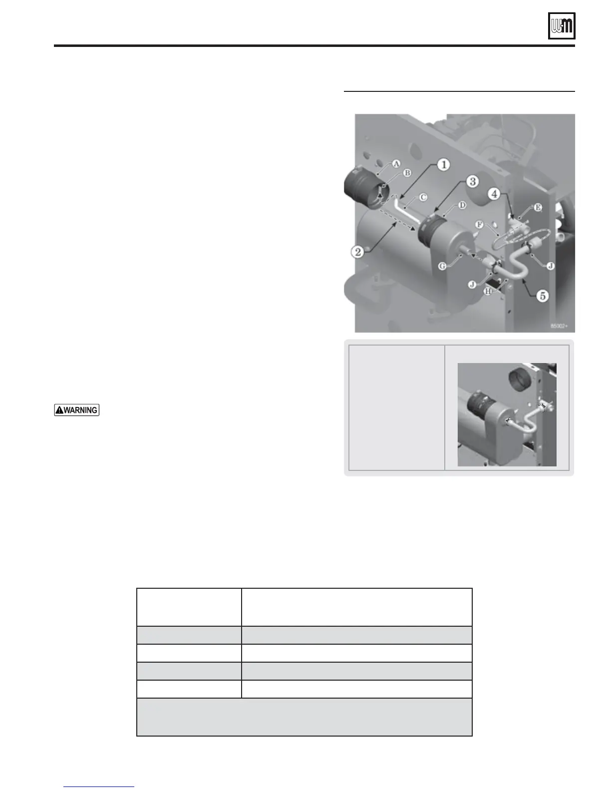
&IGURE Install condensate trap
! In-line flue drain
" Flue drain nipple
# Flue drain hose
$ Flue connection
% Condensate trap tee
& U-clamp and nuts (not
shown)
' Condensate drain
nipple
( Condensate trap hose
* Hose clamps
&INISHEDASSEMBLY
Install condensate trap
1. Before placing the boiler in position, install the condensate trap
line, shown in Figure 7. Items shown are provided with the boiler.
3TEP Attach the flue drain hose (C) to the in-line flue drain
nipple (B).
3TEP Slide a screw driver or pencil through the condensate
drain nipple (G).
Slide the end of the screwdriver or pencil into the open
end of the flue drain hose (C).
Feed the in-line flue drain (A) assembly into the flue con-
nection (D), guiding the flue drain hose through the con-
densate drain nipple (G) with the screwdriver or pencil.
3TEP Press the in-line flue drain (A) into the flue connection
(D) and through the seal ring until it reaches the stop.
Then tighten the flue connection hose clamp to secure.
The flue drain hose (C) should now extend down past the
end of the condensate drain nipple (G).
3TEP Slide the U-clamp (F) over the condensate trap tee (E)
and into the two holes in the rail. Attach the two nuts pro-
vided to the U-clamp and tighten to secure the condensate
trap tee to the rail.
3TEP Slide the ends of the condensate trap hose (H) onto the
condensate drain nipple (G) and the condensate trap tee
(E). Secure the condensate trap hose at each end with the
hose clamps (J).
#HECKTHEHEIGHTOFTHECONDENSATETRAPTEEOUTLET.
Before rotating the boiler into position, measure the
distance from the condensate tee outlet to the bottom
of the boiler mounting rails. When the boiler is place in
position, the condensate tee outlet must be higher than
the condensate pump inlet connection (when a con-
densate pump is used). Increase the foundation height
if necessary.
GV90+ Series 2 GAS-FIRED WATER BOILER — Boiler Manual
GV90+ Suggested Condensate Pump Capacity
The table below contains the suggested condensate pup capacities foe GV90+
boilers. The values below are calculated with assuming all the water vapor
in the flue gases is condensed along a 1" per hour rain load and safety factor.
Boiler Model
Minimum recommended condensate
pump capacity, per boiler, GPH
GV90+ 3 2
GV90+ 4 3
GV90+ 5 4
GV90+ 6 5
Note:
The above values can vary depending on the location of the instal-
lation and operating conditions.
Prepare the boiler (continued)