Part number 550-142-903/1016
79
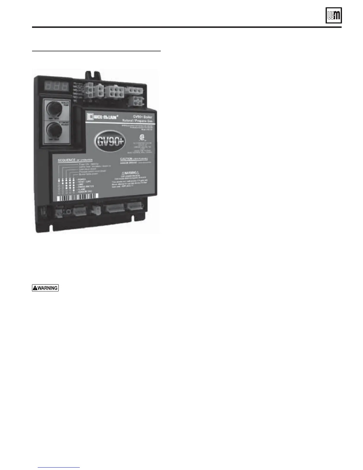
Control indicator lights —
HARD LOCKOUT Summary (Flashing LED’s)
MAY remove 120VAC power for more than 2 seconds to clear lockout OR
ignition control will automatically restart sequence of operation after 1 hour
waiting period after fault condition is cleared.
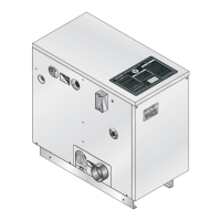
&IGURE GV90+ Integrated Boiler Control (IBC)
IBC (Integrated Boiler Control)
Make sure GROUND WIRING is installed per wiring
diagram. Good grounding is extremely important for
proper operation.
3OLDERORWATER splatter between plugs
and circuit board can cause improper
operation of IBC. Place a shield over the
boiler internal controls and components
during installation. Failure to comply
could result in severe personal injury,
death or substantial property damage.
IBC indicator lights — lockout
modes
s See Charts 1 through 7 in this section for detailed
trouble-shooting procedures.
s To reset control after a lockout, turn off power
at the 120 VAC service switch or turn down all
thermostats. Wait 45 seconds. Then restore power
and call for heat.
s After an over-temperature lockout (POWER and
LIMIT lights flashing), the control will only reset
after interruption of 120 VAC for 45 seconds. (And
temperature at return water temperature sensor
must be below 240°F.)
0/7%2LIGHTmASHINGALONE
s Usually indicates reversed polarity of 120 VAC power wires.
0/7%2AND434!4#)2#LIGHTSmASHING
s Usually indicates stray voltage on external thermostat circuit wires or
return water temperature entering boiler sections has not reached 130°F
within 30 minutes.
0/7%2AND02%3337)4#(LIGHTSmASHING
s Usually indicates pressure switch is closed when it should not be, or pres-
sure switch failed to close within 5 minutes of blower starting.
0/7%2AND&,!-%LIGHTSmASHING
s Flame sensed without a call for heat or out of sequence during ignition trial.
s Usually indicates control has had three unsuccessful ignition attempts
or sensed flame when it shouldn’t be there. Boiler may not be properly
grounded.
&,!-%LIGHTSmASHING
s Flame loss, or flame not sensed during trial for ignition. Boiler may not
be properly grounded.
3OLID3%.3/2'.$LIGHTAND,#/ONDISPLAY
s Sensor ground open. Indicates the sensor ground wire is not grounded
or the boiler has a poor ground connection or stray voltage on ground.
Check both sensor ground wire on the P5 connection and the boiler
ground.
3ENSOR'ROUNDLIGHTmASHINGALONE
s Three (3) rapid pulses indicates the sensor ground wire may not be
connected or the boiler has a poor g round connection or stray
voltage on ground.
IBC indicator lights — non-lockout modes
434!4#)2#LIGHTmASHINGALONE
&REEZE0ROTECTION
s Usually indicates return water temperature sensor detects water at boiler
return pipe less than 40°F. Both internal circulators will run continuously,
even with no call for heat, until temperature rises.
,)-)4LIGHTmASHINGALONE
s Usually indicates an open or shorted return water or supply temperature
sensor.
4ROUBLESHOOTINGTHE)"#
s See Figure 93, page 80 for location of harness plug receptacles and plugs
on the IBC.
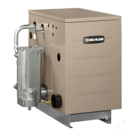
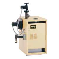
GV90+ Series 2 GAS-FIRED WATER BOILER — Boiler Manual
Troubleshooting (continued)
INDICATOR LIGHT CONDITION
POWER
Flashes once per second
120 VAC connection to boiler
earth ground.
Flash code 2* Internal fault, microprocessor or
memory.
Flash code 3* Unused.
Flash code 4* Unused.
Flash code 5* Internal fault, water thermistors
disagree.
Flash code 6*
Flashes once per second
Internal fault, gas valve circuit.
followed by 2 seconds off, then repeats.