Part number 550-142-903/1016
61
Check for gas leaks
Before starting the boiler, and during initial opera-
tion, use a leak detector or smell near the floor and
around the boiler for gas odorant or any unusual
odor. Remove boiler front door and smell interior
of boiler enclosure. Do not proceed with startup
if there is any indication of a gas leak. Repair any
leak at once.
DO NOT adjust or attempt to measure gas valve
outlet pressure except where instructed specifi-
cally in this manual. This setting is suitable for
natural gas and propane, requiring no field ad-
justment. Attempting to alter or measure the gas
valve outlet pressure without following the correct
procedures could result in damage to the valve,
causing potential severe personal injury, death or
substantial property damage.
Propane boilers only — Your propane supplier
mixes an odorant with the propane to make its
presence detectable. In some instances, the odor-
ant can fade, and the gas may no longer have an
odor. Before startup (and periodically thereafter),
have the propane supplier verify the correct odor-
ant level in the gas.
Verify gas/air orifice plate
4HEPROPERORIlCEPLATEMUSTBEUSED. Failure to do
so will cause severe personal injury, death or substantial
property damage.
1. Remove the jacket front panel.
2. Read the boiler size written on the gas/air orifice label tab, verifying
the correct size. See Figure 5, page 8 for details.
3. The orifice plate must be plain aluminum for natural gas. For
propane gas, the exposed tab of the plate should be red.
4. Replace the orifice plate if necessary, following the guidelines on
page 8.
Check thermostat circuit(s)
1. Disconnect the two external wires connected to the boiler thermo-
stat terminals (see Field wiring, beginning on page 56 for terminal
locations).
2. Connect a voltmeter across these two incoming wires. Close each
thermostat, zone valve and relay in the external circuit one at a
time and check the voltmeter reading across the incoming wires.
3. There should NEVER be a voltage reading.
4. If a voltage does occur under any condition, check and correct the
external wiring. (This is a common problem when using 3-wire
zone valves.)
5. Once the external thermostat circuit wiring is checked
and corrected if necessary, reconnect the external ther-
mostat circuit wires. Allow the boiler to cycle.
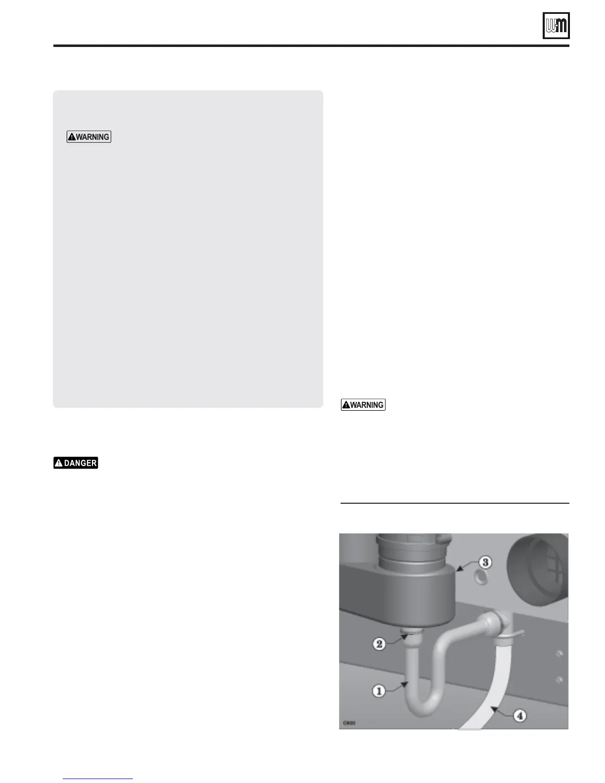
Inspect/fill condensate system
)NSPECTCHECKCONDENSATELINESANDlTTINGS
1. Inspect the condensate drain line, condensate PVC fit-
tings and condensate trap.
&ILLCONDENSATETRAPWITHWATER
1. Loosen the hose clamp (Figure 71, item 2) that secures
the condensate trap (Figure 71, item 1) to the bottom
of the recuperator (Figure 71, item 3).
2. Pull the condensate trap tube off of the recuperator
condensate drain nipple.
3. Use a funnel to feed water into the top of the conden-
sate tube.
4. Continue filling until water begins to flow out through
the condensate line (Figure 71, item 4).
5. Re-attach the condensate trap to the bottom of the
recuperator. Secure with the hose clamp.
6. Check for any leaks in the condensate drain line or fit-
tings. Repair any leaks.
7. Remove the temporary clamp (see step 2, above) from
the condensate drain tube.
The condensate trap must be filled with water
during all times of boiler operation to avoid
flue gas emission from the condensate drain
line. Prime the condensate trap by pouring
water into the outlet tee while restricting flow
in drain tube if boiler has been out of service
for an extended period. Failure to fill the trap
could result in severe personal injury or death
GV90+ Series 2 GAS-FIRED WATER BOILER — Boiler Manual
Start-up (continued)
&IGURE Condensate trap assembly