Part number 550-142-903/1016
55
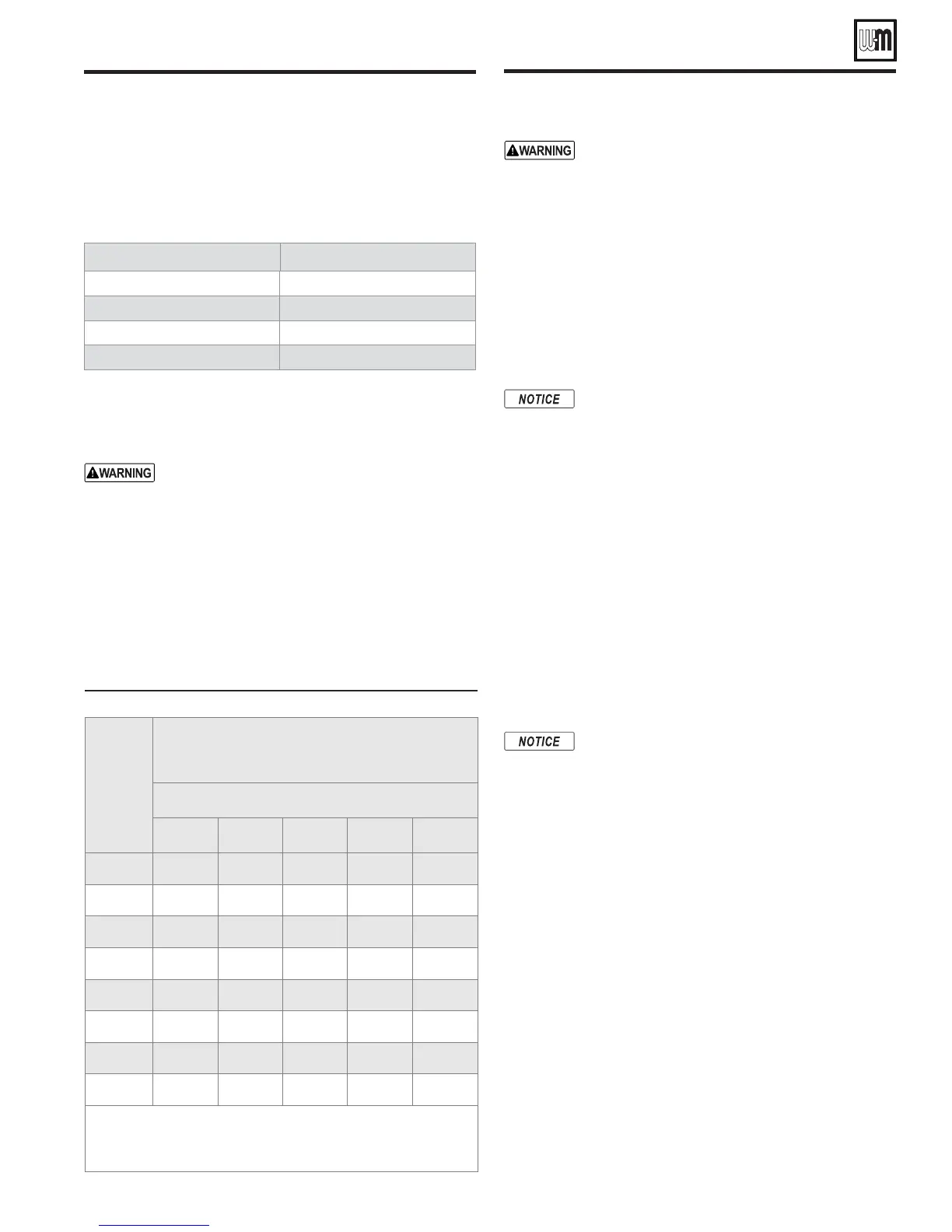
&IGUREPipe capacity for 0.60 specific gravity natural gas
'ASPIPE
LENGTH
FEET
#APACITYINCUBICFEETOFGASPERHOUR
.ATURALGASONLYWITHSPECIlCGRAVITYOF
"ASEDONPRESSUREDROPOFvWC
Gas pipe diameter —
v Ðv v v v
10
132 278 520 1050 1600
20
92 190 350 730 1100
30
73 152 285 590 860
40
63 130 245 500 760
50
56 115 215 440 670
75
45 93 175 360 545
100
38 79 150 305 460
150
31 64 120 250 380
&ORADDITIONALGASPIPESIZINGINFORMATIONREFERTO!.3):.&0!
54 (or Natural Gas and Propane Installation Code,
B149.1 or B149.2 for
Canadian installations).
For your safety, turn off electrical power supply at
service entrance panel before making any electrical
connections to avoid possible electric shock hazard.
Failure to do so can cause severe personal injury or
death.
)NSTALLATIONMUSTCOMPLYWITH
National Electrical Code and any other national, state, provincial
or local codes or regulations. In Canada, CSA C22.1 Canadian
Electrical Code Part 1, and any local codes. Boiler must be elec-
trically grounded as required by National Electrical Code ANSI/
NFPA 70 - latest edition.
Wiring must be N.E.C. Class 1. Boiler must be elec-
trically grounded as required by National Electrical
Code ANSI/NFPA 70 - latest edition.
To replace wiring, order complete harness assem-
blies from Weil-McLain. If any original wiring as
supplied with boiler must be replaced, and a har-
ness is not immediately available, use only type
105°C wire or equivalent. Use this wiring only as a
temporary repair. Obtain a complete harness from
Weil-McLain.
Wiring connections
0OWERWIRING
Connect 120 VAC power wiring as shown in . The junction box
is located on the inside left jacket panel.
Watch the polarity of the circuit when connect-
ing the 120 VAC power wiring. If the polarity is
switched, the integrated boiler control will lockout.
The IBC will flash the POWER light to indicate
this problem. See the troubleshooting information
beginning on page 76.
!DDITIONALLIMITCONTROLS
Wire additional limit controls (if used) as shown in Fig-
ure 67, page 56.
Thermostat(s)
Install thermostats on inside walls, away from influences of
drafts, hot or cold water pipes, lighting fixtures, television, sun
rays, or fireplaces.
Follow instructions with thermostat. If it has a heat anticipator,
set heat anticipator in thermostat to match power requirements
of equipment connected to it (ignition control and gas valve, zone
valve contacts, etc.). Wiring diagram on boiler gives setting for
standard equipment (ignition control and gas valve).
GV90+ Series 2 GAS-FIRED WATER BOILER — Boiler Manual
Natural Gas
1. Refer to Figure 65 for pipe length and diameter. Size gas
supply piping for total flow to all connected appliances. For
each GV90+ boiler, provide for the following gas flow (cfh =
cubic feet per hour):
"OILERMODEL #&(NATURALGAS
GV90+3 70
GV90+4 105
GV90+5 140
GV90+6 175
2. Inlet pressure required at gas valve inlet:
s maximum 14” w.c.
s minimum 3.5” w.c.
Install 100% lockup gas pressure regulator in sup-
ply line if inlet pressure exceeds 14” water column.
Adjust for 14” w.c. maximum.
Propane Gas
1. Contact gas supplier to size pipes, tanks and 100% lockup
gas pressure regulator.
2. Adjust propane supply regulator provided by gas supplier for
14” w.c. maximum pressure.
3. Inlet pressure required at gas valve inlet:
s maximum 14” w.c.
s minimum 3.5” w.c.
Gas piping (continued)
Wiring