Part number 550-142-903/1016
74
4OCLEANTHEBURNER
The burner may contain ceramic fiber par-
ticles. Use care when handling these materials
per instructions on page 106 of this manual.
Failure to comply could result in severe per-
sonal injury.
1. Clean the burner ports with a soft brush.
2. Use compressed air to blow out any particulate if neces-
sary. Use caution to avoid particulate being blown into
the building.
4OREPLACEBLOWERASSEMBLY
1. Place a new blower flange gasket over the studs at com-
bustion chamber opening.
2. Reinstall burner cone into chamber opening.
3. Position blower assembly over studs. Install nuts and
tighten.
4. Install igniter and new igniter gasket. Fasten with screws
and washers. Tighten only with hand-held screwdriver.
DO NOT use electric or pneumatic driver. Excessive
torque will damage igniter. Do not exceed 20 inch-
pounds torque.
5. Connect:
a. Gas valve and piping (4 screws)
b. Gas tubing to gas valve outlet
c. Pressure switch hoses
d. Hose from gas valve to gas/air manifold
e. Air inlet hose
f. Blower motor wiring harness to IBC
g. Igniter harness to igniter plug
h. Blower support bracket (with screw)
i. Ground wire.
6. Be sure all wiring and hose connections are correct
per Figure 81, page 73 and are secure on the hose barb
fittings.
Inspecting and cleaning the recuperator
Turn off power and gas to the boiler. Failure to
do so can cause severe personal injury, death
or substantial property damage.
Wait several minutes after boiler has stopped
to allow the boiler components to cool to
avoid severe personal injury or death.
2EMOVINGCLEANINGREINSTALLINGTHE
RECUPERATOR
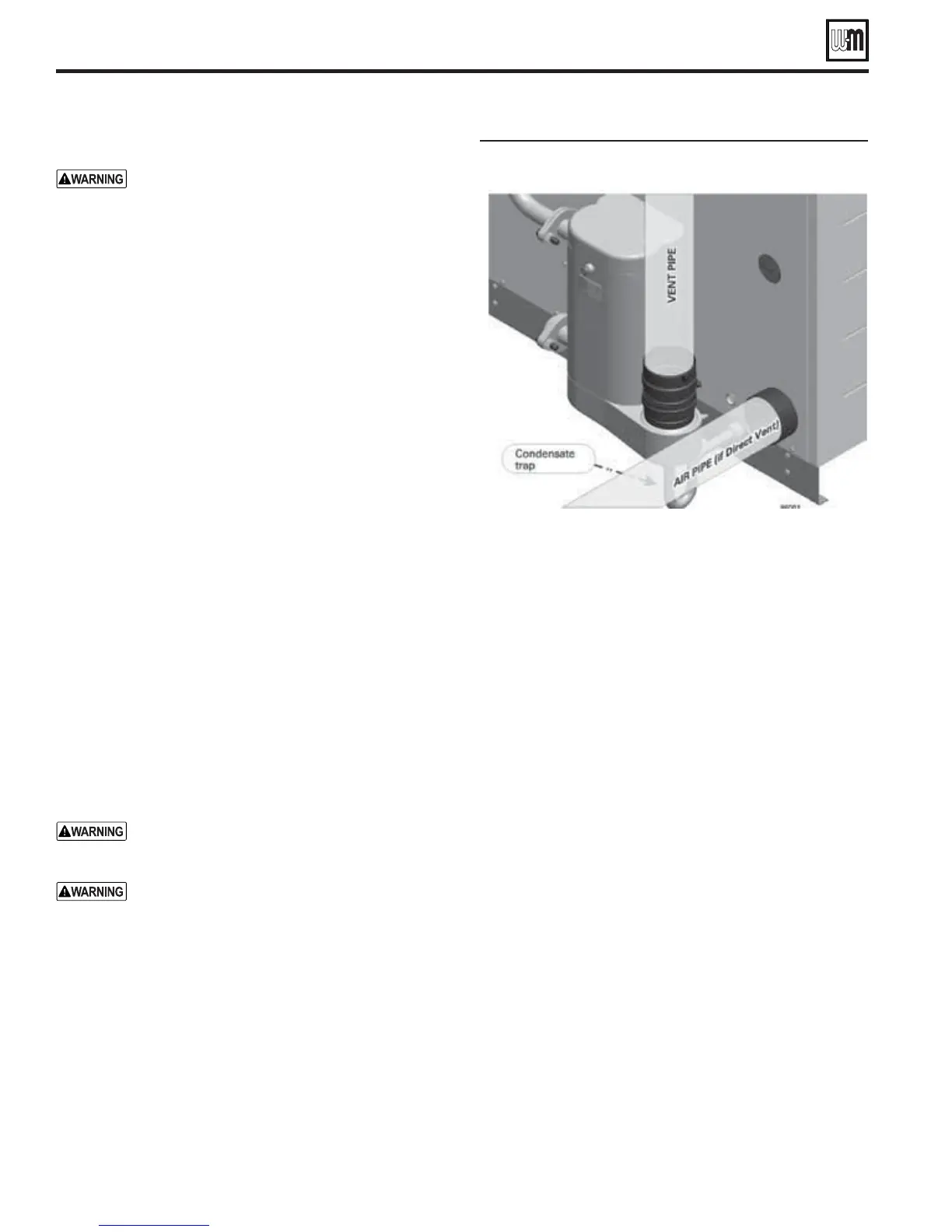
$ISCONNECTTHEVENTPIPEFROMTHERECUPERATOR
1. The vent pipe must be disconnected (at the in-line flue
drain, item A in Figure 7, page 9).
2. If the vent piping can be moved enough, loosen the flue
pipe clamp on the in-line flue drain. Then lift the flue
pipe up and move aside slightly.
&IGURE Recuperator access and cleaning
3. If the vent piping cannot be moved, then cut the flue pipe
carefully so a coupling can be inserted later, or remove a
section of vent pipe if using stainless vent pipe.
)SOLATEBOILERANDDRAINPARTIALLY
1. Remove the jacket top panel and front panel.
2. Allow time for the boiler to cool down if it has been op-
erating.
3. Close the isolation valves on the boiler supply and return
connections.
4. The boiler will have to be partially drained.
a. Place a large pan under the boiler drain valve.
b. Slowly open the drain valve and allow about a gallon of
water to drain out.
c. Place the pan under the water connection flanges on
the recuperator.
d. Loosen the upper recuperator flange and allow any water
in the line to run out.
e. Loosen the lower recuperator flange (return connec-
tion) and allow the water in the line and recuperator
to drain out.
5. After the recuperator and water lines have been drained,
disconnect both recuperator flanges.
2EMOVETHERECUPERATOR
1. See Figure 102, page 97. Loosen the (4) nuts that secure the
recuperator to the boiler.
2. Disconnect the plug-in connector on the thermal fuse (Fig-
ure 102, page 97, item 27).
3. Carefully slide the recuperator off of the (4) studs.
4. Loosen the flue adapter clamp and remove the in-line drain
fitting from the flue adapter.
5. Manipulate the recuperator so that the flueway (Figure 82)
and tubes of recuperator (internal tubes not shown) maybe
GV90+ Series 2 GAS-FIRED WATER BOILER — Boiler Manual
Service & maintenance (continued)