Part number 550-142-903/1016
104
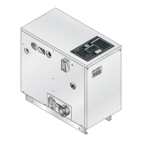
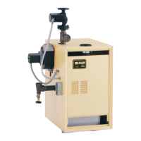
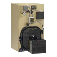
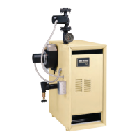
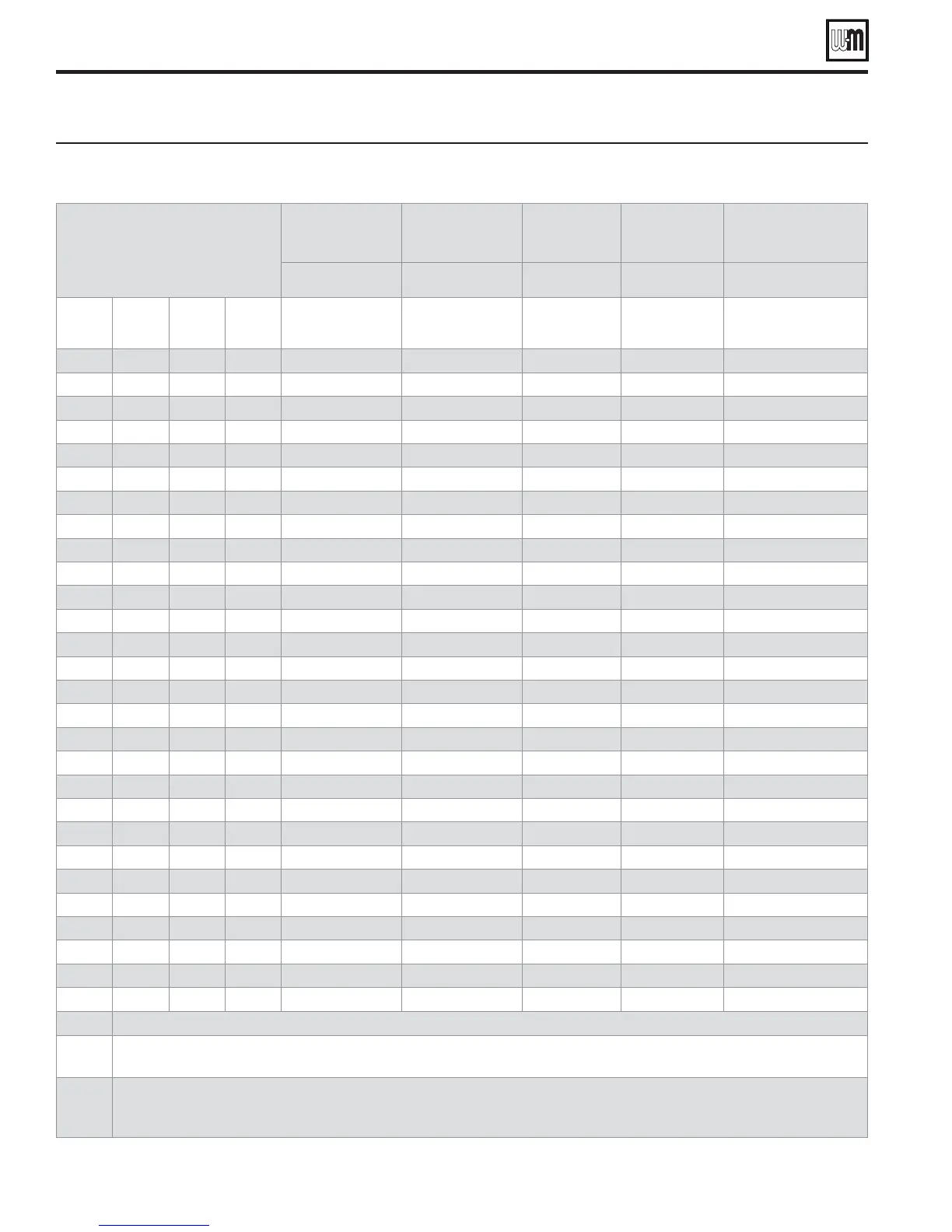
&IGURE Multiple GV90+ boilers — ratings and engineering data — maintain the clearances shown on pages 6 and 7 —
see Figure 28, page 23 and Figure 29, page 23 for layout options
"OILERSINSYSTEM
-ODEL'6
4OTAL
#3!
INPUT
$/%(EATING
CAPACITY
"OILER
(0
.ETWATER
RATINGS
-ANIFOLDED
COMBUSTIONAIR
DUCTSIZE
Input,
MBH
Output,
MBH
- MBH
Square
inches
3456
- Note 1 - Note 2
Note 3
Figure 37, page 31
2 140 130 3.9 112 70
2 210 194 5.8 168 105
2 280 260 7.8 226 140
2 350 322 9.6 280 175
3 210 195 5.8 168 105
3 315 291 8.7 252 158
3 420 390 11.7 339 210
3 525 483 14.4 420 263
4 280 260 7.8 224 140
4 420 388 11.6 336 210
4 560 520 15.5 452 280
4 700 644 19.2 560 350
5 350 325 9.7 280 175
5 525 485 14.5 420 263
5 700 650 19.4 565 350
5 875 805 24 700 438
6 420 390 11.7 336 210
6 630 582 17.4 504 315
6 840 780 23.3 678 420
6 1050 966 28.9 840 525
7 490 455 13.6 392 245
7 735 679 20.3 588 368
7 980 910 27.2 791 490
7 1225 1127 33.7 980 613
8 560 520 15.5 448 280
8 840 776 23.2 672 420
8 1120 1040 31.1 904 560
8 1400 1288 38.5 1120 700
Note 1
Based on standard test procedures outlined by DOE for individual boilers.
Note 2
Net AHRI ratings are based on piping and pickup allowance of 1.15.
Consult Weil-McLain Technical Services for other allowances.
Note 3
All GV90+ installations require a separate vent pipe and termination for each boiler. 6ENTPIPINGCANNOTBEMANIFOLDED. Install and
terminate vents as described in vent/air installation instructions in this manual.
Combustion air piping can be individually piped or manifolded. See Figure 37, page 31, for manifolded air piping.
GV90+ Series 2 GAS-FIRED WATER BOILER — Boiler Manual
Dimensions and ratings (continued)