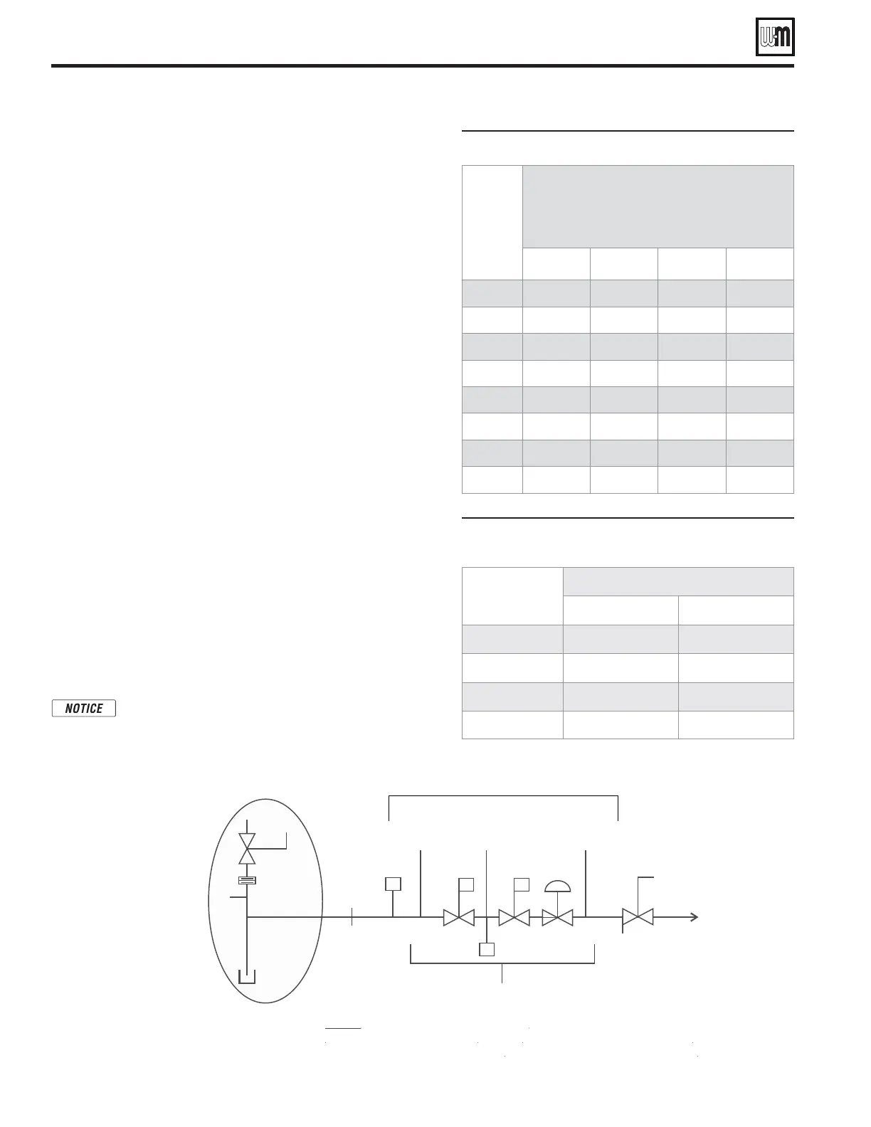
Figure 48 Pipe capacity for natural gas
Gas
pipe
total
length
(feet)
Gas supply pipe capacity (cubic feet per
hour)
@ 0.30” w.c. pressure drop
EWDKEHGGVRGTJQWTURGEKſEITCXKV[
2” 2½” 3” 4”
10 3050 4800 8500 17500
20 2100 3300 5900 12000
30 1650 2700 4700 9700
40 1450 2300 4100 8300
50 1270 2000 3600 7400
70 1050 1700 3000 6200
100 870 1400 2500 5100
150 710 1130 2000 4100
Figure 49 Equivalent lengths of straight pipe for gas
line fittings
0IPESIZE
inches
%QUIVALENTLENGTHFEET
90° Elbow Tee
2”
5.17 10.3
2½”
6.16 12.3
3”
7.67 15.3
4”
10.1 20.2
Gas piping (continued)
SVF
™
Series 1
Commercial Condensing Gas-Fired Water Boiler
— Boiler Manual
Part number 550-100-250/0819
48
Pipe sizing for Natural Gas
1. Size gas supply piping from meter outlet to entrance of boiler in ac-
cordance with Figure48 and Figure49.
2. Use the total input of all connected appliances. Divide the total input in
Btuh by 1,000 to obtain approximate cubic feet per hour of natural gas.
a. Pipe lengths in Figure48 are equivalent lengths of straight pipe. Use
Figure49 to determine equivalent length of ings.
b. Figure48 is only for natural gas with specic gravity 0.60, with a
pressure drop through the gas piping of 0.30” w.c.
c. For additional gas pipe sizing information, refer to ANSI Z223.1/
NFPA 54 - latest edition (or Natural Gas and Propane Installation
Code - CAN/CSA B149.1 for Canadian installations).
Pipe sizing for propane gas
Contact gas supplier to size pipes, tanks and 100% lockup gas pressure
regulator. Gas pipe must be properly sized with a 100% lockup gas pressure
regulator in the gas supply line. An undersized gas pipe feeding the boiler(s)
can cause problems.
Multiple boiler applications —manifolded
gas supply lines
1. Size gas supply piping as instructed above.
2. At each boiler, provide a manual shuto gas valve, union and sediment
trap (minimum 3 inches below tee) as shown in Figure46, page47.
3. Ensure the piping is large enough so that the minimum pressure at
each boiler, with all connected appliances ring, will be as specied
on page47.
Gas pressure switches
1. SVF
TM
boilers are equipped with manual reset high gas pressure and
low gas pressure switches (see Figure47, page47).
2. ese switches are factory set and should remain at the following set-
tings:
a. High gas pressure: 14inches w.c.
b. Low gas pressure: 2inches w.c.
e low gas pressure switch must be manually reset (buon
on front of switch) on initial startup or any time the gas supply
is turned o.
Gas Train Diagram
+
0
81,21
3
%2,/(5
&211(&7,21
3
6$0(
9$/9(%2'<
/
33
665
3
0
),(/'3,3,1*±*$6
7$%/(
6 6$)(7<6+87±2))9$/9(
5 =(52*29(51255(*8/$725
0 0$18$/6+87±2))9$/9(
/ /2:*$635(6685(6:,7&+
+ +,*+*$635(6685(6:,7&+
3 35(6685(7$3
#2 #3
#1
From Figure47, page47.
 Loading...