Home
Weir
Water Pump
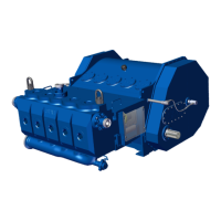
Warman 650 M200-MCR-G
Weir Warman 650 M200-MCR-G - User Manual
287 pages
Manual
Go to English
Specs
Ask a question
Save Page as PDF
To Next Page
To Next Page
Loading...
2
Table of Contents
Main Page
Español
19
Table of Contents
19
Introducción
21
General
21
Identificación de
21
Cimientos
23
Alineamiento del Eje
23
Alineamiento, Tensionado y Ajuste de Transmisión de Correas en V
23
Alineamiento de Bombas Acopladas Directamente
26
Tuberías
28
Bridas
28
Operación
29
General
29
Sello del Eje
29
Cebado
30
Revisión de Rotación de Motor
30
Destrabado del Eje
30
Puesta en Marcha Normal de Bomba
31
Puesta en Marcha
32
Tubería de Admisión
32
Aire Ingresando en la
32
Fallas de Funcionamiento
32
Nivel Bajo de Pozo de Bomba
32
English
114
Basic Instructions
115
Delivery
115
General Instructions
115
Introduction
115
Storage
115
Foundation
116
Installation
116
Mechanical Aspects
116
Types of Bases
116
Alignment
117
Coupling
117
Electrical Aspects
118
Power Supply System
118
Starting of Electric Motors
118
Motor Protection
119
Operation
120
Preliminary Inspection
120
Start-Up
120
Stopping
120
The First Start-Up
120
Cleanliness
121
Lubrication
121
Lubrication Instructions
121
Lubrication Intervals
121
Maintenance
121
Quality and Quantity of Grease
121
Abnormal Situations During Operation
122
Miscellaneous Recommendations
122
Replacement of Bearings
122
General Technical Data
141
Technical Data
141
Weights
142
Measuringsurface Soundpressure Level
144
Measuringsurface Soundpressure Level for Bevelhelical Gear Units (B
144
Measuringsurface Soundpressure Level for Bevelhelical Gear Units (B
145
Measuringsurface Soundpressure Level for Helicalgear Units (H
146
Measuringsurface Soundpressure Level for Helicalgear Units (H
147
Copyright
148
General Notes
148
Introduction
148
Obligations of the User
149
Proper Use
149
Safety Instructions
149
Environmental Protection
150
Special Dangers and Personal Protective Equipment
150
Scope of Supply
151
Transport
151
Transport and Storage
151
Storing the Gear Unit
153
Standard Coating and Preservation
154
Exterior Preservation
155
Interior Preservation with Preservative Agent
155
General Description
156
Technical Description
156
Housing
157
Output Designs
157
Lubrication
161
Pressure Lubrication through Addon Oilsupply System
161
Splash Lubrication
161
Toothed Components
161
Labyrinth Seals
162
Radial Shaftsealing Rings
162
Shaft Bearings
162
Shaft Seals
162
Taconite Seals
163
Tacolab Seal
164
Backstop
165
Torquelimiting Backstop (Special Design)
166
Cooling
167
Fan
167
Cooling Coil
168
Addon Oilsupply System with Air Oilcooler
169
Addon Oilsupply Unit with Water Oilcooler
171
Filter
172
Heating
172
Pump
172
Water Oilcooler
172
Oiltemperature Monitoring
173
Oillevel Monitoring System
174
Bearingmonitoring System
175
Speed Transmitter
175
Auxiliary Drive
176
Auxiliary Drive, Designed as a Maintenance Drive
176
Auxiliary Drive, Designed as a Load Drive
177
Overrunning Clutch
178
Fitting
179
General Information on Fitting
179
Description of Installation Work
180
Foundation
180
Installation of Gear Unit on Housing Base
180
Unpacking
180
Alignment Surfaces, Alignment Thread
181
Mounting on a Foundation Frame
182
Mounting on a Concrete Foundation by Means of Stone Bolts or Foundation Blocks
183
Mounting on a Concrete Foundation by Means of Anchor Bolts
184
Assembly of a Shaftmounting Gear Unit with Hollow Shaft and Parallel Keyway
185
Preparatory Work
185
Axial Fastening
186
Fitting
186
Demounting
187
Fitting
189
Preparatory Work
189
Shaftmounting Gear Unit with Hollow Shaft and Internal Spline to DIN 5480
189
Axial Fastening
190
Fitting with Integrated du Bush
190
Fitting with Loose du Bush
190
Demounting
191
Fitting
192
Shaftmounting Gear Unit with Hollow Shaft and Shrink Disk
192
Axial Fastening
193
Fitting with Integrated du Bush
193
Fitting with Loose du Bush
193
Fitting the Shrink Disk
194
Shrink Disk
194
Cleaning and Greasing the Shrink Disk
196
Demounting the Shrink Disk
196
Inspection of the Shrink Disk
197
Remounting the Shrink Disk
197
Couplings, Clutches
198
Shaftmounting Gear Unit with Flanged Shaft
199
Shaft Mounting Gear Unit with Block Flange
200
Attaching the Torque Arm
201
Mounting the Torque Arm for the Gear-Unit Housing
201
Attaching the Support
202
Mounting Supports for Gearunit Swing Bases
202
Bearingmonitoring System
203
Gear Unit with Addon Components
203
Gear Unit with Heating Element
203
Gear Unit with Oil-Temperature Monitoring System
203
Gear Unit with Oillevel Monitoring
203
Gear Unit with Speed Transmitter
203
Gear Units with Air Oilcooler
203
Gear Units with Cooling Coil
203
Gear Units with Fitted Water Oilcooler
203
Final Work
204
Screwconnection Classes
204
Screwconnection Classes, Tightening Torques and Initial Tensioning Forces
204
Tightening Torques and Initial Tensioning Forces
205
Procedure before Startup
206
Removal of Preservative Agent
206
Startup
206
Filling with Lubricant
208
Oil Quantities
209
Gear Unit with Cooling Coil or External Oilsupply System
210
Oil Level
210
Startup
210
Gear Unit with Backstop
211
Gear Unit with Overrunning Clutch
211
Temperature Measurement
211
Bearing Monitoring (Vibration Measurement)
212
Checking Procedure
212
Heating
212
Oillevel Monitoring System
212
Removal from Service
212
Exterior Preservation
213
Exteriorpreservation Procedure
213
Interior Preservation During Longer Disuse
213
Interior Preservation with Gear Oil
213
Interior Preservation with Preservative Agent
213
Interiorpreservation Procedure
213
General
214
Irregularities
214
Oil Level
214
Operation
214
Faults, Causes and Remedy
215
General Information on Faults and Malfunctions
215
Possible Faults
215
General Notes on Maintenance
217
Maintenance and Repair
217
Change Oil
218
Description of Maintenance and Repair Work
218
General Oil-Service Lives
218
Test Water Content of Oil
218
Clean the Air Filter
219
Check Cooling Coil
220
Clean the Fan and Gear Unit
220
Refill Tacolab Seals with Grease
220
Refill Taconite Seals with Grease
220
Check Air Oilcooler
221
Check Hose Lines
221
Check Tightness of Fastening Bolts
221
Check Water Oilcooler
221
Checking Auxiliary Drive
221
Checking Friction Linings of Torquelimiting Backstop
221
Top up Oil
221
Final Work
222
General Inspection of the Gear Unit
222
Lubricants
222
Spare Parts and Customerservice Addresses
223
Spare Parts, Customerservice Addresses
223
Stocking Spare Parts
223
Declaration of Incorporation
224
Identification/Name Plate
277
Intended Use
277
Safety Instructions
278
Accessories
279
Design & Functional Description
279
Design, Main Components, Materials
279
Allow. Media
280
Ambient Conditions
280
Functional Ranges, Operation Conditions
280
Operating Data
280
Transportation
281
Operating Advice
282
Shutting down / Dismantling
282
Causes of Faults / Removal of Faults
283
Environmental Protection / Disposal
283
Maintenance
283
Technical Data
284
Need help?
Do you have a question about the Weir Warman 650 M200-MCR-G and is the answer not in the manual?
Ask a question
Weir Warman 650 M200-MCR-G Specifications
Print Specification
General
Size
650
Category
Water Pump
Manufacturer
Weir
Configuration
Horizontal
Model
650 M200-MCR-G
Type
Slurry Pump
Related product manuals
Weir Warman 650 M200-MCR-G-RR
287 pages
Weir ROTO-JET R0
37 pages
Weir SPM TWS600S
41 pages
Weir Roto-Jet RO III 3x2
40 pages
Weir SPM QWS 2500
42 pages
Weir SPM QWS 2500 XL
44 pages
Weir ROTO-JET 2100
37 pages
Weir ROTO-JET RG
37 pages