Do you have a question about the WEISS BWD250390K01R0901SI and is the answer not in the manual?
Lists the individual modules that make up the controller system.
Provides fundamental safety guidelines for operation and handling.
Covers electrical hazards and safe operating conditions.
Explains the necessity of an emergency stop circuit for safety.
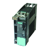
Describes the design and features of the power modules.
Details interfaces and connections for frame size FSA.
Details interfaces and connections for frame size FSB.
Lists the technical specifications for PM240-2 power modules.
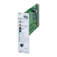
Describes the safety relay used for safety functions.
Lists the technical specifications for the safety relay.
Describes the control unit.
Lists the technical specifications for the control unit.
Details the available software input signals.
Details the available software output signals.
Details assignments for D410-2 interfaces.
Explains built-in SIL2 safety features.
Discusses achieving SIL3 with additional measures.
Details the mounting and connection process.
Instructions for mounting power modules.
Provides dimensions and hole patterns for power modules.
Dimensions for specific frame sizes.
Dimensions for frame size EF2300.
Detailed steps for module mounting and connection.
Guidelines for EMC-compliant installation and cable routing.
Specifics for 1-phase power connection.
Specifics for 3-phase power connection.
Specifics for higher power 3-phase connection.
Instructions for connecting the motor, including EMC considerations.
Motor connection diagram for FSA frame.
Motor connection diagram for FSB frame.
Steps for mounting the brake relay.
Instructions for mounting the safety relay.
Instructions for mounting the control unit.
Guides through the machine configuration process.
Guides through configuring the rotary indexing table.
Manual configuration process.
Configuration using a data file.
Guides through configuring the interfaces (inputs/outputs).
Manual I/O configuration process.
Adjusting dynamic parameters for table movement.
Monitoring and controlling the device during operation.
Operating the rotary indexing table manually.
Measuring and setting quick stop parameters.
Optimizing stop delay time.
Provides a detailed list of error codes, causes, and remedies.
| Brand | WEISS |
|---|---|
| Model | BWD250390K01R0901SI |
| Category | Controller |
| Language | English |