Do you have a question about the WEISS EF2 Series and is the answer not in the manual?
Describes the EF2...B controller's purpose, features, and benefits for rotary indexing tables.
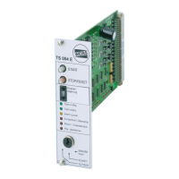
Illustrates and lists the individual modules that make up the EF2 controller system.
General safety principles, operator obligations, and compliance requirements.
Details electrical safety, grounding, and precautions against hazardous voltages.
Highlights the necessity of an emergency stop circuit for immediate shutdown.
Lists potential risks and hazards associated with controller components.
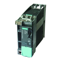
Describes the design, features, and safety instructions for PM240-2 power modules.
Information on the optional external braking resistor, including technical data.
Description and technical data for the motor contactor used in the system.
Description and technical data for the safety relay.
Description of the TM15 module for digital inputs and outputs.
Description and technical data for the brake relay.
Description and technical data for the SIMOTION D410-2 control unit.
Details on the function and default configuration of software input signals.
Details on the function and default configuration of software output signals.
Pinout and description for D410-2 control unit interfaces.
Pinout and description for TM15 terminal module interfaces.
Overview of integrated safety functions meeting SIL2 requirements.
How to achieve SIL3 safety category using additional measures.
Instructions for installing the optional external braking resistor.
Proper assembly and mounting of PM240-2 power modules.
Rules and guidelines for EMC-compliant cable routing and installation.
Procedures and necessary measures for connecting the motor cable.
Instructions for mounting and dismounting the SIMOTION D410-2 control unit.
Configuration of network settings on the PC for controller connection.
Details on establishing Ethernet communication using TCP/IP.
Description of the controller's web interface start page and its areas.
Step-by-step guide for configuring the machine parameters.
Procedure for configuring the controller's input and output interfaces.
Monitoring controller inputs, outputs, and system status.
Operating the rotary indexing table manually.
Functionality and setup of hardware limit switches for movement range limitation.
Procedure for connecting the controller via Profibus DP using SIMATIC.
Procedure for connecting the controller via Profinet IO RT using SIMATIC.
Lists the status messages of the rotary indexing table.
Explanation of the LED displays on the SIMOTION D410-2.
Detailed table of error messages, their causes, and remedies.
Information regarding CE conformity and EC Directives.
Details on EMC compliance and requirements for Category C3.
Information on cULus safety approvals and regional compliance.
Wiring diagrams for EF2...B controllers with 0.37 kW power modules.
Wiring diagrams for EF2...B controllers with 1.5-3.0 kW power modules.
An index listing all illustrations and figures within the manual.
An alphabetical index of topics covered in the manual.
| Brand | WEISS |
|---|---|
| Model | EF2 Series |
| Category | Controller |
| Language | English |