Do you have a question about the WEISS TS 002 E and is the answer not in the manual?
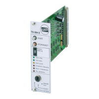
These instructions apply to control cards in the model series: TS 002 E, TS 003 E, TS 004 E.
Covers emergency stop procedures, required protective devices, and the product's designated use and compliance.
Explains how the TS004 E card controls cam indexing tables, optimizing time and supporting manual/PLC operation.
Provides key technical specifications including operating voltage, power consumption, digital inputs/outputs, EMV, temperature ranges, and dimensions.
Details the function, level, comment, and multipoint plug connection for each terminal on the control card.
Explains the function of Terminal 1 (Rotation direction), Terminal 2 (Enable/Reset/Stop), Terminal 3 (Start edge), Terminal 5 (Stop), Terminal F (Sensor).
Details specific inputs like Manual Brake Control (G), Status-Controlled Start (H), and Temperature Monitoring (T).
Details the function of Terminal 4 (Automatic), 6 (Alarm), 7 (Alarm), 8 (Sum of alarms), 9 (Start permitted), 10 (Table in position), C, D, E.
Explains the function of the START key, STOP/RESET key, and the rotary switch for stop delay.
Details stop delay configuration via rotary switch and explains operating mode selection (Automatic, Inching, Release brake).
Details installation options including card holder for DIN rail, terminal PCB, and built-in housing.
Presents the overall circuit diagram showing connections between the TS 004 E, electronic contactor, motor, brake, and sensor.
Details the motor line switching via electronic relay and E-Stop contactors, including wire size and contactor versions.
Explains how alarms are indicated (red LED, outputs 6, 7, 8) and how to reset them using the STOP key or terminal 2.
Provides a table listing fault texts, corresponding output states, and potential causes for diagnosis.
Includes the EC Manufacturer's Declaration according to the Machine directive and lists applicable EC directives and harmonised standards.
| Brand | WEISS |
|---|---|
| Model | TS 002 E |
| Category | Controller |
| Language | English |