Manual R06-201644 / 172
ROTARY INDEXING TABLE CONTROLLER EF2...B
FUNCTION AND SIGNAL DESCRIPTIONS | 4.5 Interface assignment D410-2
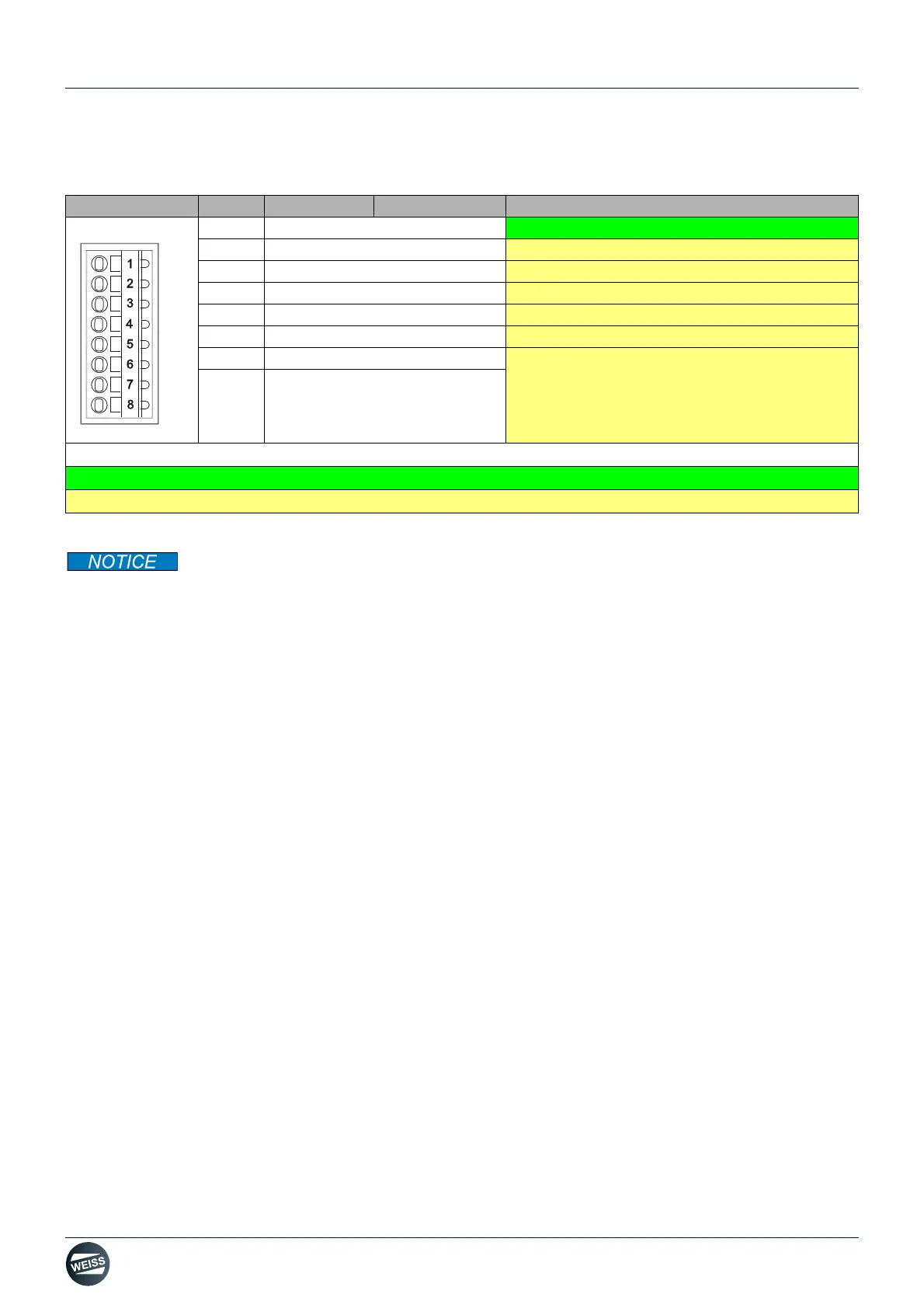
4.5.6 Interface X131
The common mode range must not be exceeded. This means that the analog differential voltage
signals can have a maximum offset voltage of ±12 V with respect to the reference potential. If the range limits are
exceeded, incorrect results may occur during analog/digital conversion.
A 24 V supply voltage must be connected to terminal X124 for the digital outputs to be used.
If momentary interruptions in the voltage occur in the 24 V supply, the digital outputs will be deactivated in the mean
time.
Representation Pin Name Description
1 DI/DO 12
Feedback 24-V power supply of brake relay
2 DI/DO 13
Do not use
3M
Do not use
4 DI/DO 14
Do not use
5 DI/DO 15
Do not use
6M
Do not use
7 AI 0+
Do not use
8
AI 0-
Colour coding in the description:
Green: relevant for EF2
Yellow: Not used for EF2. Do not use!