23 WAS.handling Electro Documentation
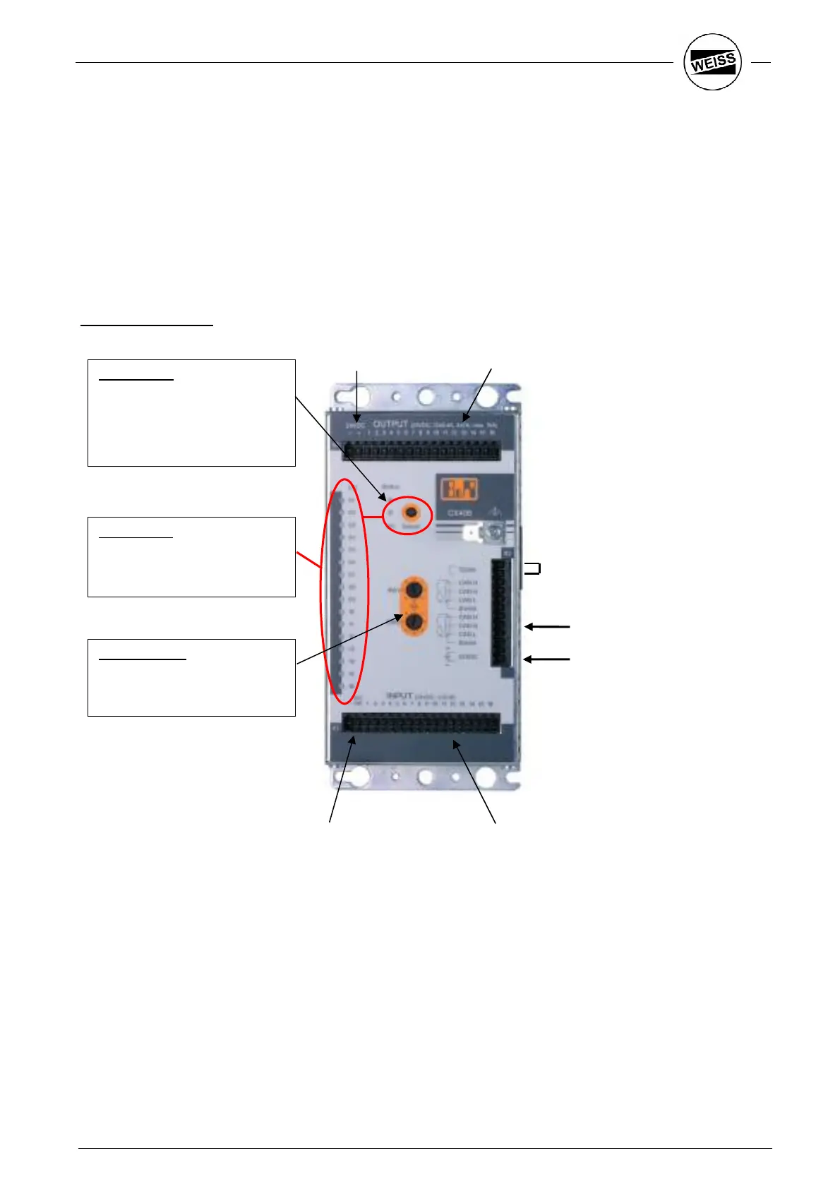
3.4 Electrical installation of I/O-Module
One or two I/O-Modules can be applied. The connection to the drives takes place via the internal CAN-Bus.
Adequate cables are within the shipment.
One Module has 16-In- and 16-Outputs, 24VDC.
Outputs 1-12 can supply up to 0,4A, the Outputs 13-16 can supply up to 2A. The sum of all currents is max.
10A.
Control elements:
Status LED:
green: normal operation
green flash.: startup
red: RESET
red flash.: wrong node number
orange: faulty output
orange flash.: supply outputs
I/O-Monitor:
Use the ‘Select’ key to toggle
between the display of the inputs
(green) and the outputs (red).
24V supply for the
I/O -Module
Bridge: Terminating resistor
CAN-Bus
CAN-Bus
24V-supply
Outputs
Outputs 1...16
Inputs 1...16
24V-supply for
Inputs
'-' -> GND
'DC OK' -> +24V
Rotary switch:
Setting the CAN-Address:
SW1: C
SW0: C