5
2
1
3
4
5
6
7
8
9
10
12
18
15
11
13
14
16
17
19
20
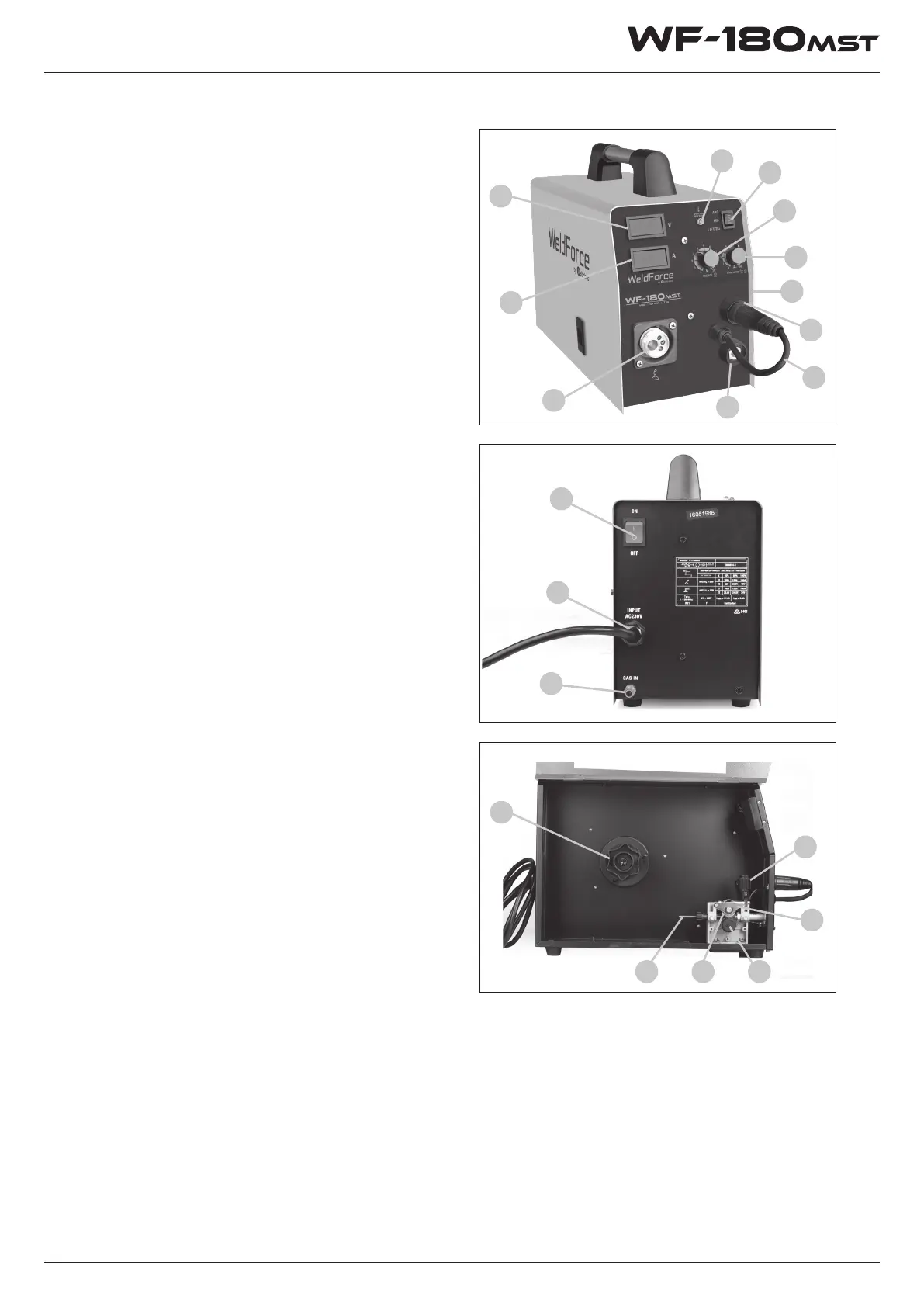
Know Your Machine
Controls Explained
1. MIG Torch Euro Connection
2. LCD current meter - Displays output current
(amps) in real time*
3. LCD Voltage meter - Displays output voltage
in real time*
4. Welding voltage adjustment knob - Adjusts
welding voltage in MIG mode*
5. MIG wire feed speed adjustment knob/
Arc (Stick / TIG) current adjustment knob*
6. Overload Indicator Lamp*
7. Welding output mode switch. Sets power
source in MIG, MMA or Lift TIG mode*
8. Cooling Fan Inlet (obscured)
9. MIG Torch Polarity Connection Lead
10. Negative (-) welding power output
connection socket
11. Positive (+) welding power output
connection socket (obscured)
12. Shielding Gas Inlet Connection
13. 240V AC mains power input lead
14. Mains power switch
15. Wire spool holder
16. Wire drive inlet guide
17. Wire feed tension adjustment
18. Wire feed tension arm
19. Wire drive roller retainer
20. Wire drive roller (obscured)
These indicate the actual voltage and current
readings at the output terminals of the welding
machine. The current meter should read ‘0’ except
when welding is actually taking place. The voltage
meter will indicate output voltage during welding
and the welding open circuit voltage when the
machine is powered up but not welding. In MIG
mode the open circuit voltage will only appear
once the torch is triggered to activate the circuit,
LCD Current & Voltage Display Meters
in MMA and Lift TIG mode, the open circuit voltage
will show on the display continuously. The digital
meters are very sensitive and accurate, so it is not
abnormal to observe some small uctuations on
them when the machine is at rest.