4
4
5
5
.
.
P
P
l
l
a
a
c
c
i
i
n
n
g
g
i
i
n
n
t
t
o
o
O
O
p
p
e
e
r
r
a
a
t
t
i
i
o
o
n
n
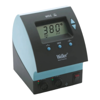
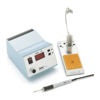
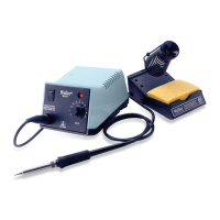
Take care when unpacking the unit and accessories.
Place the soldering tool in the Tool Holder. Insert the
soldering iron plug into the iron receptacle (8) on the
front of the control unit and lock by turning clockwise.
Verify the supply voltage matches the specification on
the Base Unit Label and that the Power Switch (7) is
Off. Connect the Power Cord into the receptacle (9) on
the rear of the control unit and plug into a properly
grounded power receptacle. Switch On the unit at the
Power Switch (7). The unit performs a self-test when it
is switched “On”, whereby all LCD Icons are briefly dis-
played (1).
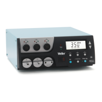
Following the self test, the “Set” temperature is dis-
played for a brief period. The electronic system then
switches automatically to the “Read” value. The “
~”
symbol appears and the three fixed temperatures of
Radio Buttons
I
I
,
I
I
I
I
and
I
I
I
I
I
I
are displayed. The “~” sym-
bol serves as a Heater Control Indicator. When fully illu-
minated, the system is heating up. Flashing indicates
the “Set” temperature has been reached and the tool
temperature has stabilized.
5
5
.
.
1
1
T
T
e
e
m
m
p
p
e
e
r
r
a
a
t
t
u
u
r
r
e
e
S
S
e
e
t
t
t
t
i
i
n
n
g
g
5
5
.
.
1
1
.
.
1
1
S
S
e
e
t
t
t
t
i
i
n
n
g
g
T
T
e
e
m
m
p
p
e
e
r
r
a
a
t
t
u
u
r
r
e
e
w
w
i
i
t
t
h
h
U
U
P
P
/
/
D
D
o
o
w
w
n
n
S
S
c
c
r
r
o
o
l
l
l
l
K
K
e
e
y
y
s
s
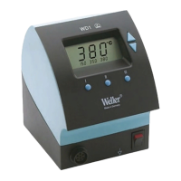
As a rule, the main display (1) shows the tip tempera-
ture (“Read”) value. By depressing the
U
U
P
P
or
D
D
O
O
W
W
N
N
Scroll Keys (2 & 3), the display switches to the current
“Set” value. The temperature symbol flashes
°
°
F
F
(or
°
°
C
C
)
)
.
The “Set” value can now be changed by tapping or
holding in the
U
U
P
P
or
D
D
O
O
W
W
N
N
Scroll Key (2) (3). If the
Scroll Key is held depressed, the “Set” value changes
rapidly. Approximatly 2 seconds after the button is
released, the display switches automatically back to
the “Read” value.
5
5
.
.
1
1
.
.
2
2
S
S
e
e
t
t
t
t
i
i
n
n
g
g
T
T
e
e
m
m
p
p
e
e
r
r
a
a
t
t
u
u
r
r
e
e
w
w
i
i
t
t
h
h
t
t
h
h
e
e
R
R
a
a
d
d
i
i
o
o
B
B
u
u
t
t
t
t
o
o
n
n
s
s
I
I
,
,
I
I
I
I
,
,
I
I
I
I
I
I
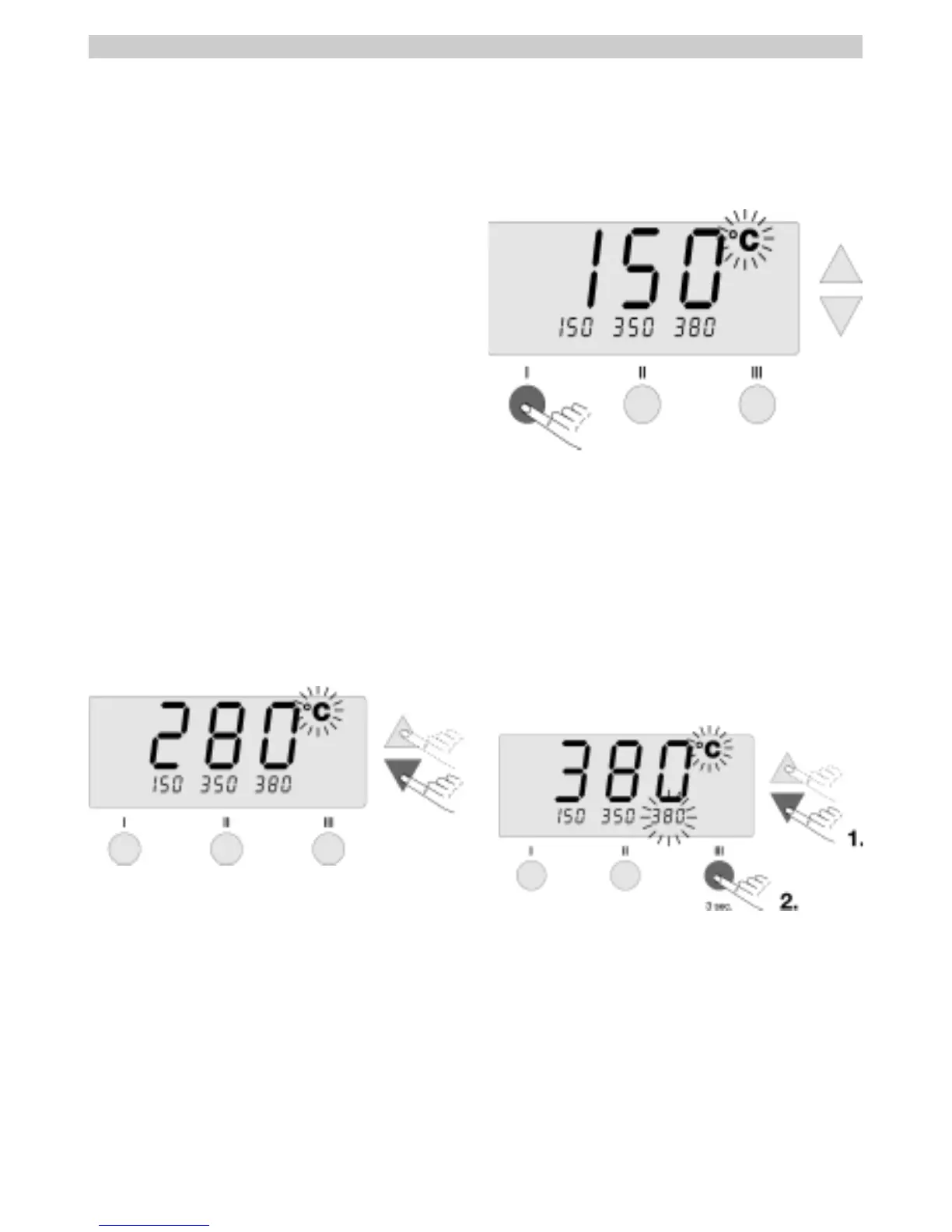
The “Set” temperature can also be changed via the 3
Radio Buttons
I
I
,
,
I
I
I
I
,
,
I
I
I
I
I
I
.
Default settings:
I
I
300 °F ( 150 °C )
I
I
I
I
660 °F ( 350 °C )
I
I
I
I
I
I
720 °F ( 380 °C )
By depressing a Radio Button, the pre-selected value
for that button now becomes the “Set” temperature.
The new value appears for approximatly 2 seconds in
the display and the temperature symbol flashes
°
°
F
F
(
(
or
°
°
C
C
)
)
. The display then switches back automatically to
the “Read” value.
5
5
.
.
1
1
.
.
3
3
C
C
h
h
a
a
n
n
g
g
i
i
n
n
g
g
P
P
r
r
e
e
s
s
e
e
t
t
V
V
a
a
l
l
u
u
e
e
s
s
o
o
f
f
R
R
a
a
d
d
i
i
o
o
B
B
u
u
t
t
t
t
o
o
n
n
s
s
I
I
,
,
I
I
I
I
,
,
I
I
I
I
I
I
The 3 Radio Buttons
I
I
,
,
I
I
I
I
,
,
I
I
I
I
I
I
can be preset with temper-
ature values as desired.
Depress the
U
U
P
P
or
D
D
O
O
W
W
N
N
Scroll Key to set a desired
temperature (see 5.1.1) in the large display. The
°
°
F
F
(or
°
°
C
C
)
)
temperature symbol flashes
.
.
Next, depress and hold the desired Radio Button
I
I
,
,
I
I
I
I
or
I
I
I
I
I
I
. While the button is depressed, the small display
assigned to the Radio Button also flashes and, after 3
seconds, accepts the value of the large display.
Release the Radio Button.
Setting a Radio Button to a low temperature gives you
the option of manually and quickly decreasing temper-
ature when the soldering iron is not being used.
6
6
.
.
S
S
p
p
e
e
c
c
i
i
a
a
l
l
F
F
u
u
n
n
c
c
t
t
i
i
o
o
n
n
s
s
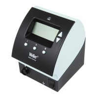
The special functions are divided into two menu sec-
tions:
Special Function Menu 1:
Often used functions such as;
STANDBY (Temp.), OFFSET (Temp.), SETBACK (Time),
etc.
Special Function Menu 2:
F
actor
y Control Check (FCC)
and REMOTE ID.
E
E
n
n
g
g
l
l
i
i
s
s
h
h
 Loading...