5. Instructions for use
For initial heating, coat the selective tinnable tip with sol-
der. This removes any oxidation or dirt on the tip which
may have occurred during storage. During pauses bet-
ween soldering and before storing the soldering iron,
ensure that the tip of the soldering iron is well coated. Do
not use aggressive fluxing agents.
Note:
Always ensure the proper position of the soldering iron
tip.
These soldering irons have been adjusted for an average-
size tip. Deviations can occur due to exchanging of the tip
or using other tip designs.
External input unit WCB 2 (optional)
The following functions are possible when using an
external input unit.
Offset: The real temperature of the soldering iron
can be changed by ± 40 °C by input of a
temperature offset.
Setback: Reduction of the setpoint temperature to
150 °C (standby). The setback time can be
set at 0-99 minutes after the soldering sta-
tion has switched to standby mode. After a
period equal to three times the set-back
time, the ”Auto Off” function is activated.
The soldering iron is switched off (flashing
dash on the display).
Lock: Locking the setpoint temperature. Settings
cannot be changed after the soldering sta-
tion has been locked.
°C/°F: Switching the temperature display from °C
to °F, and vice versa.
Window: Limitation of the temperature range to
max. ±99 °C based on a locked
temperature resulting from the ”LOCK”
function. The locked temperature repre-
sents the median point of the adjustable
temperature range.
For units with a floating contact (opto-
coupler output) the ”WINDOW” function is
used to adjust a temperature window. If
the actual temperature is within the tempe-
rature window the floating contact will be
enabled (optocoupler output).
Cal: Re-adjustment of the soldering station
(WCB 2 only).
PC interface: RS232 (WCB 2 only).
Temp. gauge: Integrated temperature gauge for ther
mal element Type K (WCB 2 only).
6. Accessories
005 29 161 99 Soldering iron set WSP 80
005 33 131 99 Soldering iron set MPR 80
005 33 112 99 Soldering iron set LR 21, antistatic
005 33 113 99 Soldering iron set LR 82
005 33 155 99 Soldering iron set WMP
005 33 133 99 Soldering iron set WTA 50
005 27 028 99 Preheating plate WHP 80
005 25 030 99 Thermal insulating unit WST 20
005 31 180 99 External input unit WCB 2
WPHT Stop and go iron stand (WMP)
WPH80T Stop and go iron stand (WSP 80)
7. Scope of supply
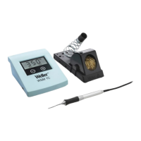
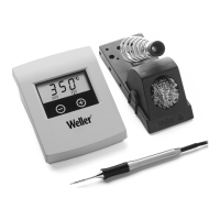
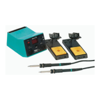
WSD 81 WSL
Control unit Control unit
Soldering iron WSP 80 Soldering iron WMP
Power cable Power cable
Operating instructions Operating instructions
Soldering iron rest Soldering iron rest
Jack (not USA) Jack (not USA)
Safety Information Safety Information
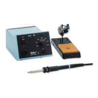
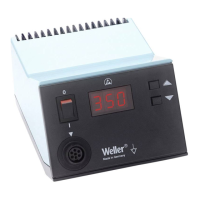
PUD 80
Control unit
Power cable
Operating instructions
Jack (not USA)
Safety Information
Illustration: Circuit diagram, see Page 62
Illustration: Exploded view, see Page 63/64
Subject to technical change without notice!
15
English