Startup
Assure free-travel of the Displacer and Displacer Arm by rocking the
Torque Bar by hand and observing corresponding movement of
Displacer. The Displacer Arm should be centered in the vessel
nozzle to assure that the vessel nozzle does not inhibit free
operation. Displacer Arm should be parallel to the ground at
installation.
The controller is factory-set for average level and sensitivity.
- Increase the compression of the Spring by
turning theAdjustment Wheel to the
LEVELADJUSTMENT
To DECREASE LEVEL
RIGHT.
SETTING INTERFACE LEVEL
NOTE: The
presence of foam in the interface zone may affect the accuracy
of the control.
The controller is factory-set for average level and sensitivity.
Generally speaking, interface operation is most successful when
there is a substantial differential in specific gravity between the two
liquids. Interface cannot be reliably achieved with a displacer-type
control with specific gravity differentials less than 0.1. Also, the
sensitivity of the interface control is increased by the size of the
displacer. Therefore, it is usually advantageous to use the largest
displacer available, which will fit into the vessel.
The Company, L.L.C. Oklahoma City, Oklahoma Tel: (405) 672-6660 Fax: (405) 672-6661
wellmarkco.com
© The WellMark Company • Litho USA • All registered trademarks are the property of their respective owners. • IOM-2001NB 091007
4
2001NB
Series
psipsi
DECREASE LEVEL
by increasing Spring compression
ADJUSTMENT WHEEL
SPRING
RIGHT
psipsi
ADJUSTMENT WHEEL
SPRING
psipsi
INCREASE LEVEL
by decreasing Spring compression
ADJUSTMENT WHEEL
SPRING
LEFT
To INCREASE LEVEL -
LEFT.
Decrease Spring compression by turning
theAdjusting Wheel to the
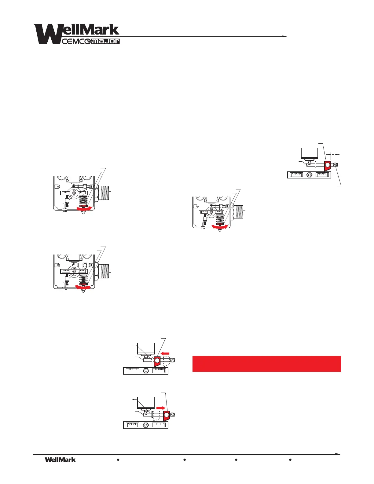
ADJUSTING PROPORTIONAL BAND (SPAN)
To DECREASE BAND
(Increase Sensitivity)
Loosen Thumbscrew on Fulcrum and position the Fulcrum along the
Flapper Bar.
Slide Fulcrum along
Flapper Bar toward
Snap Ring.
FULCRUM
PILOT
FLAPPER
BAR
SNAP
RING
FULCRUM
PILOT
FLAPPER
BAR
SNAP
RING
To INCREASE BAND
(decrease Sensitivity)
Slide Fulcrum along
Flapper Bar away from
Snap Ring.
Once desired band/span is achieved re-tighten Thumbscrew.
FULCRUM
PIVOT
PILOT
FLAPPER
BAR
1”
2
1. Set Fulcrum approx. 1/2” from
pivot pin.
Reduce Spring tension slowly by
turning the Adjusting Wheel to the
Allow the upper fluid to rise until
it completely submerges the Displacer.
LEFT.
Next, fine-tune the adjustment by turning the Adjusting Wheel to
the until an output signal is attained.
Finally, turn theAdjusting Wheel back to the until the output
signal returns to
2. Allow the lower liquid to rise until the desired interface level is
attained. Fine tune by slowly turning the Adjusting Wheel to the
until an output signal is obtained. Finally, slowly turn the
Adjusting Wheel to the until the output signal returns to
ZERO.
3. To obtain a shorter dump span, slide the Fulcrum away from the
pivot and repeat the above procedure.
RIGHT
LEFT
ZERO.
RIGHT
LEFT
Maintenance
The 2001NB Level Control is designed to provide years of reliable
service. However, build up of debris, paraffin, etc inside the
controller Body can interfere with proper functioning. A regular
maintenance program should include checking for this condition.
Prior to maintenance of the 2001NB Level Control
system must be isolated from pressure. Failure to
do so may result in personal injury, environmental
spill concerns and/or damage to equipment.
WARNING!
 Loading...