ASSEMBLY AND ADJUSTMENTS
SETTING THE CUTTING SPEED (Fig. 5)
Your jig saw is equipped with a variable speed dial (Fig. 5 - 1) to set the
appropriate blade stroke rate for your operation. Speed setting 1 is the low-
est speed, and setting 6 is the highest speed (3300 RPM). To increase the
speed, turn the wheel forward to a higher number. To decrease speed, turn
the wheel backwards to a lower number.
The optimal cutting speed/stroke rate depends on the material being cut,
the type of blade being used, and the feed rate preferred by the operator.
Fig. 6
Fig. 7
Fig. 5
1
1
Fig. 4
As a general rule, use slower speeds for denser materials and use faster speeds for softer materials. To best deter-
mine the cutting speed, test on a scrap piece of identical material and adjust accordingly.
CAUTION: When the jigsaw is used at low speed settings for an extended length of time, the motor temperature
will rise due to slower speeds of the internal cooling fan. To prevent the motor from overheating, occasionally run
the tool at full speed for a few minutes to keep the motor running at high efficiency.
11
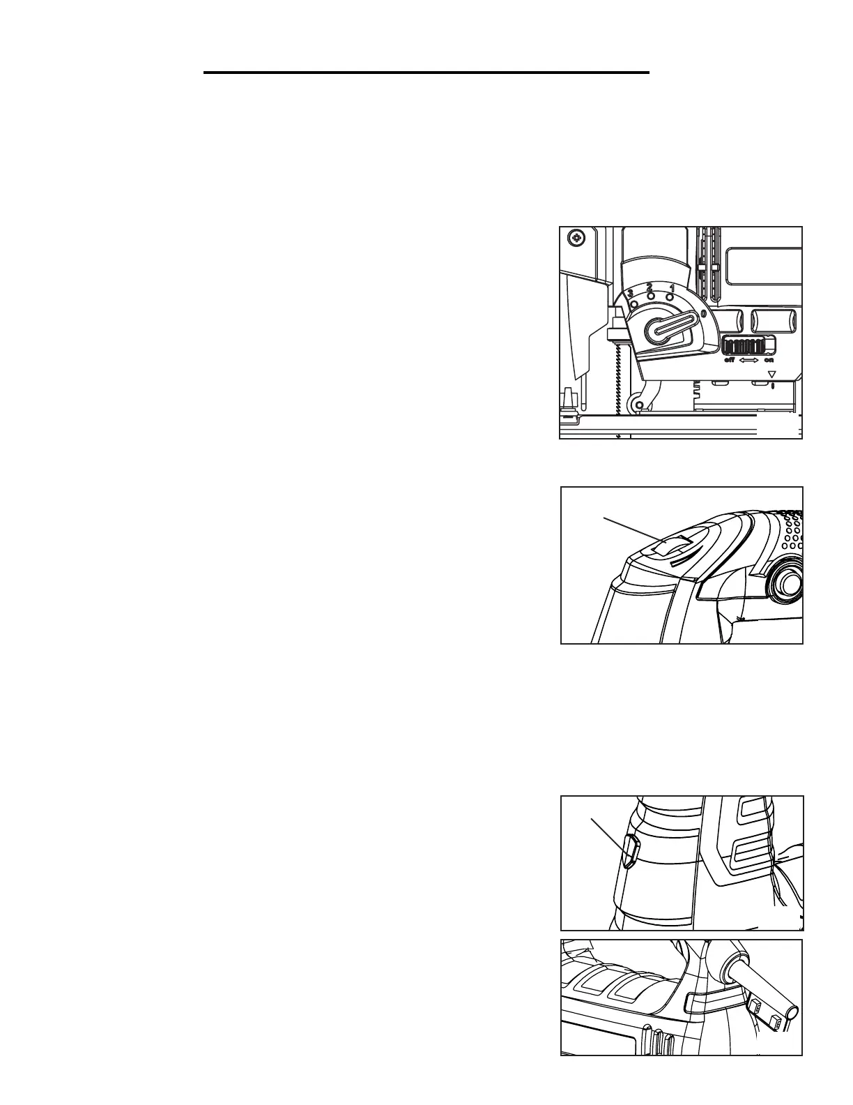
SETTING THE BLADE ORBITAL ACTION (Fig. 4)
The blade orbit selector lever controls the blade orbit travel distance. There are 4 settings, indicated on the side
housing (Fig. 4). At the 0 setting, the blade moves up and down in a straight line for smooth cutting. At the 3 setting,
the blade moves in an elliptical stroke for fast, aggressive cutting. Maximum cutting efficiency can be obtained by ad-
justing the blade orbit selector lever to suit the material being cut. This list below is guideline to help you determine
which setting to use for your application. To determine the best setting, test cuts in scrap materials first.
• Setting 0: Suits hard materials such as metals or thin sheet metals.
Use this setting for plunge cuts, as well as cutting curves and sharp edges.
• Setting 1: Suits medium-hard materials (hard wood, aluminum) and
thin workpieces. This setting can also be used for making round cuts and
sharp edge cuts.
• Setting 2: Suits soft materials such as wood and plastics where cleaner
cutting or delicate scrolling work is performed.
• Setting 3: Suits soft materials such as wood and plastics. Use this setting
for faster and more aggressive cutting.
TURNING ON THE LASER AND LED LIGHT (Fig. 6)
Your tool is equipped with a laser and LED light. Use the button on the
front of the tool (Fig. 6 - 1) to control this feature.
•Press 1: Laser (see page 7 for laser safety rules)
•Press 2: Light
•Press 3: Laser and light
•Press 4: OFF
POWER INDICATION LIGHT (Fig. 7)
The power indication light turns green when the tool is connected to the
power. If the light turns red, that mean that means the tool has diagnosed a
problem. Disconnect the tool and contact customer service for assistance.

 Loading...