WARNING! Do not plug in or turn on the tool until it is fully assembled according to the instructions. Read
through and become familiarized with the following procedures of handling and adjusting your tool. Failure to
follow the safety instructions may result in serious personal injury.
ASSEMBLY & ADJUSTMENTS
11
REMOVE THE ANTI-RUST COATING
Tool comes protected with a layer of anti-rust coating that needs
to be cleaned off before use. Wipe off coating using an acetone-
moistened cloth. Wear gloves to protect your hands. Apply a
light coat of good-quality paste wax to the bed.
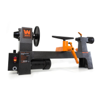
INSTALLING THE TOOL REST BASE
Before installing the handle on the tailstock end of the bed, you
must install the tool rest base.
1. Loosen the tailstock locking lever (see p. 13) and remove the
tailstock from the bed.
2. Slide the tool rest base onto the bed of the lathe.
3. Lock the tool rest base in place using the locking lever (Fig.
4 – 4) see “ADJUST THE TOOL REST” below).
Fig. 3
Fig. 4
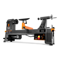
INSTALL THE TOOL REST
1. Loosen the tool rest locking handle (Fig. 4 – 3). The handle is spring-loaded and can be re-positioned as needed.
2. Insert the tool rest (Fig. 4 – 1) into the tool rest base (Fig. 4 – 2).
3. Tighten the tool rest locking handle.
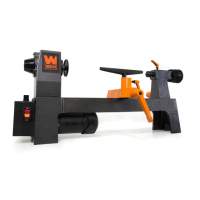
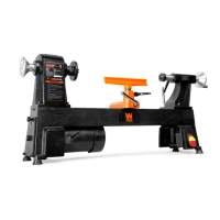
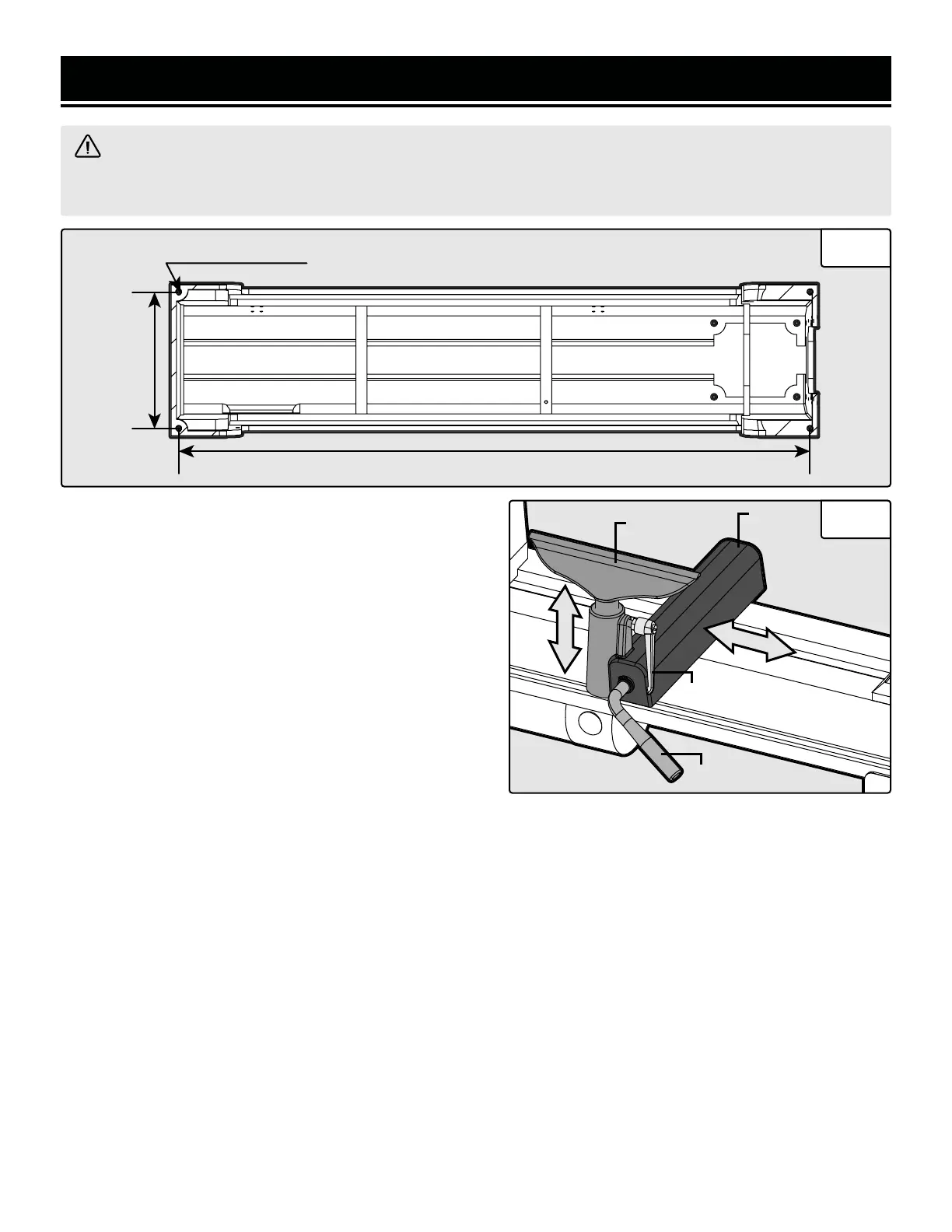
MOUNT THE LATHE TO A BENCHTOP
For safe operation, securely mount the lathe onto a secure workbench to prevent movement during operation (mounting
hardware is not included). Refer to Fig. 3 for your lathe’s base dimensions and mounting hole threads.
NOTE: If the machine is not being mounted onto a benchtop, install the 4 rubber feet into the mounting holes.
ADJUST THE TOOL REST
You can adjust the position, height and angle of the tool rest assembly to suit your task at hand.
1. The tool rest locking lever (Fig. 4 - 4) locks the tool rest base (Fig. 4 - 2) in position. Loosen the lever to slide the tool rest
base along the lathe bed. Tighten the lever firmly when the tool rest base is properly positioned.
NOTE: There is a nut on the underside of the tool rest base that needs to be adjusted periodically to enable the tool rest base
locking lever to tighten properly.
2. The tool rest locking handle (Fig. 4 - 3) locks the tool rest (Fig. 4 - 1) in place. Loosen the handle to position the tool rest
at the specific angle or height. Tighten the handle firmly when the tool rest is properly positioned.
NOTE: Adjust the height of the tool rest to just below the center of the workpiece, so that the tool will cut at the center of the
workpiece (see page 16, step 7).
44
33
11
22
855 mm
185 mm
M8-1.25x15mm
 Loading...