11
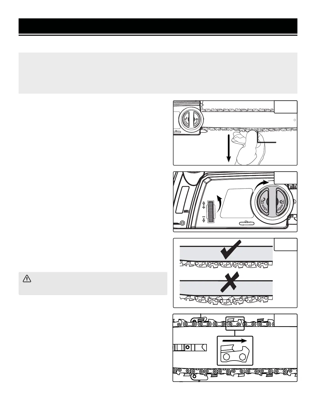
NOTE: The saw chain must be tensioned properly in order to ensure safe operation. The chain tension is optimal
if the saw chain can be lifted 1/8 inch (3 mm) from the center of the guide bar. Since the saw chain heats up
during operation, its length can therefore fluctuate. Check the chain tension every 10 minutes of operation and
adjust as necessary, particularly for new saw chains. Slacken the saw chain after the work is completed since it
shortens when cooling down. In doing so, you can elongate the chain’s life and prevent damage.
1. Check the chain tension by pulling the saw chain away from
the guide bar. A properly tensioned chain should have roughly
1/8 inch (3 mm) of distance between itself and the bar guide
(Fig. 4).
2. If adjustments are needed, loosen the cover locking knob
one full turn.
3. To adjust the saw chain tension, rotate the chain tension-
ing wheel (Fig. 5). Rotating the wheel upwards increases the
tension; rotating it downwards decreases tension. A properly
tensioned chain should have no sag (Fig. 6) and should only
be able to be pulled 1/8 inch (3 mm) away from the guide bar
of the saw.
4. Once the chain is properly tensioned, tighten the cover
locking knob. Do not over-tension the chain: this will lead to
excessive wear and reduces the life of both the bar and chain.
REPLACING THE CHAIN
1. Rotate the cover locking knob and remove the cover of the
saw’s body (see “Installing the Guide Bar and Chain” for more
details).
TENSIONING THE CHAIN
2. Lift the worn saw chain out of the fitted slot in the guide bar.
3. Place the new chain in this position, making sure the teeth
are facing the correct direction (Fig. 7) and that the edge of
the chain fits into the slot around the guide bar.
4. Replace the cover. Adjust tension before operating.
WARNING! When handling saw chains, always wear
protective gloves.
ASSEMBLY & ADJUSTMENTS
Fig. 4
1/8"
(3mm)
Fig. 5
Fig. 6
Fig. 7