ASSEMBLY & ADJUSTMENTS
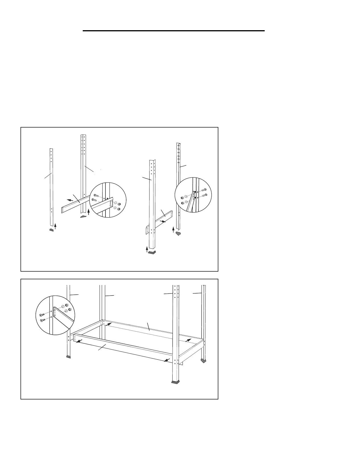
1. Installing Bottom Side
Beams (1, 2, 4)
Attach the bottom side beams (4) to
the inside of the front (1) and back
posts (2), using M6x10 bolts, washers
and nuts (B). See Figure A.
2. Attaching Rubber Feet (3)
Attach the rubber feet (3) to the bot-
tom of all 4 posts (1 & 2).
See Figure A.
3. Installing Bottom Front
& Back Beams (5)
Attach the bottom beams (5) to the
inside of the front (1) and back (2)
posts, using M6x10 bolts, washers and
nuts (B). See Figure B.
NOTE: All beams (4, 5) should be
mounted inside of the posts (1, 2). All
flanges on the beams should be fac-
ing upwards.
Page 5
Assembly Instructions
Read the ENTIRE IMPORTANT SAFETY INFORMATIONS section at the beginning of this document
including all text under subheadings therein before set up or use of this product.
Note: Unless stated otherwise, all connections are
made using Bolts, Washers and Nuts (B). Finger tighten
all connections until assembly is done. Assemble the
Workbench on a flat, level, and hard surface.
1. Attach Side Beams (4) to Front (1)
and Back Posts (2).
2. Attach Rubber Feet (3) to the bottom
of all 4 posts. (See Figure A.)
1
2
4
3
3
1
2
3
3
4
Figure A
3. Attach Bottom Beams (5) to the Front (1)
and Back (2) Posts. (See Figure B.)
5
5
2
2
1
1
Figure B
4. Attach Side Beam (4) and Side Beam with Power
Strip Opening (4A) to the top 2 holes on Front
Posts (1) and the middle 2 holes on Back Posts (2).
Note: Side Beam with Power Strip Opening can
be attached to either the right or left side.
5. Attach Power Strip (22) to Side Beam with
Power Strip Opening using U Brackets
(F) and Screws (E). (See Figure C.)
4
4A
22
E
F
E
E
E
2
2
1
1
Figure C
6. Attach Top Beams (6) to the top 2 holes
on Front Posts (1) and the middle 2 holes
on Back Posts. (See Figure D.)
Note: Make sure the Front Top Beam (6) carries
the Warning Label and is right-side up.
6
6
1
2
2
1
Figure D
Assembly of the work station requires two people. Get a good buddy (or a trustworthy foe) to help you.
Before assembly: Each part should have been labeled with its corresponding number/letter. Organize all the
parts according to the exploded view and parts list on page 6 & 7, so you can find the parts you need for each step.
Allocate sufficient space on a flat, level, and hard surface for assembly.
Tools required (not included): Phillips head screwdriver, medium drive, and 7mm, 8mm, and 10mm socket.
NOTE: Only finger tighten all fasteners during assembly to allow for adjustments. Level all components at the
end of the assembly, and THEN fully tighten all fasteners using the appropriate tools.
8
 Loading...