ASSEMBLY & ADJUSTMENTS
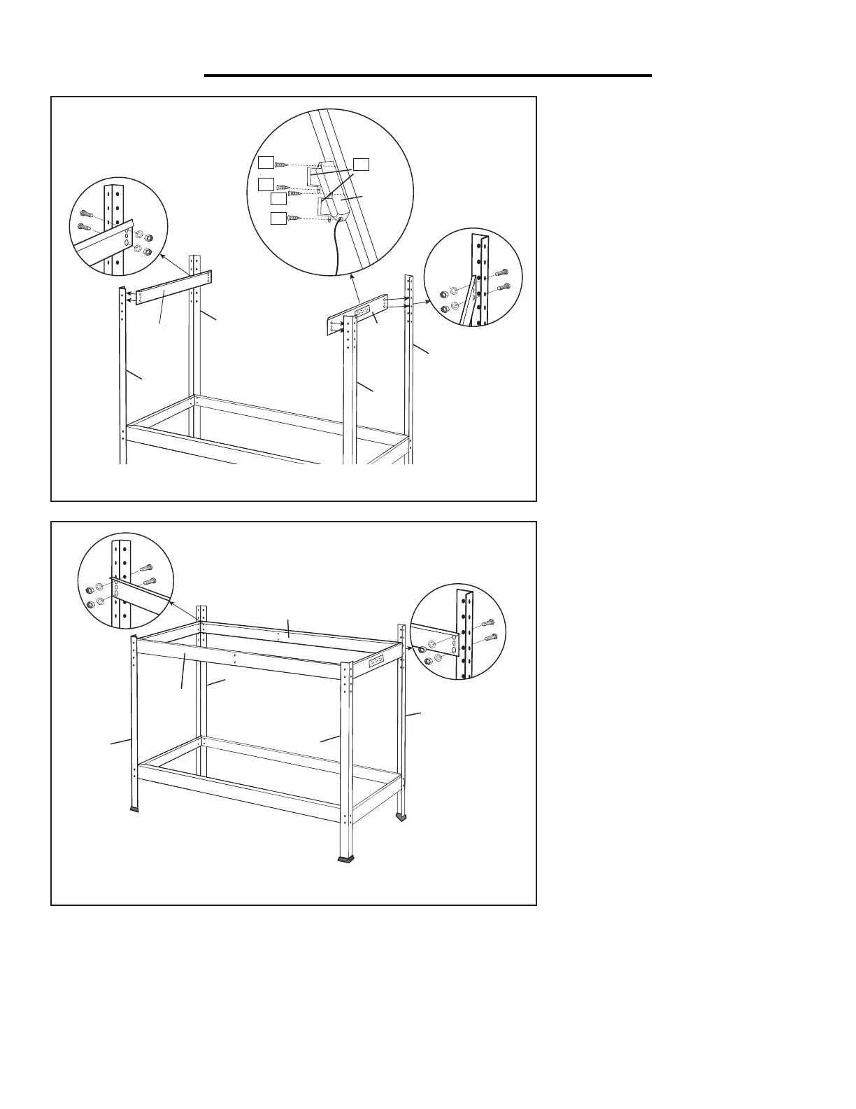
4. Installing
Upper Side Beams (4, 4A)
Attach one side beam (4) and the side
beam with power strip opening (4A)
to the top 2 holes on the front posts
(1) and middle 2 holes on the back
posts (2), using M6x10 bolts, washers
and nuts (B). See Figure C.
NOTE: The side beam with power
strip opening can be attached to
either the right or left side.
5. Attaching Power Strip (22)
Attach the power strip (22) to the side
beam power strip opening (4A), using
U brackets (F) and ST4 x 9.5 screws
(E). See Figure C.
6. Installing Upper Front &
Back Beams (6)
Attach the upper beams (6) to the
top 2 holes on front posts (1) and the
middle 2 holes on the back posts (2),
using M6x10 bolt, washer and nut (B).
See Figure D.
NOTE: All beams (4, 4A, 6) should
be mounted inside of the posts (1, 2).
All flanges on the beams should be
facing upwards.
Page 5
Assembly Instructions
Read the ENTIRE IMPORTANT SAFETY INFORMATIONS section at the beginning of this document
including all text under subheadings therein before set up or use of this product.
Note: Unless stated otherwise, all connections are
made using Bolts, Washers and Nuts (B). Finger tighten
all connections until assembly is done. Assemble the
Workbench on a flat, level, and hard surface.
1. Attach Side Beams (4) to Front (1)
and Back Posts (2).
2. Attach Rubber Feet (3) to the bottom
of all 4 posts. (See Figure A.)
1
2
4
3
3
1
2
3
3
4
Figure A
3. Attach Bottom Beams (5) to the Front (1)
and Back (2) Posts. (See Figure B.)
5
5
2
2
1
1
Figure B
4. Attach Side Beam (4) and Side Beam with Power
Strip Opening (4A) to the top 2 holes on Front
Posts (1) and the middle 2 holes on Back Posts (2).
Note: Side Beam with Power Strip Opening can
be attached to either the right or left side.
5. Attach Power Strip (22) to Side Beam with
Power Strip Opening using U Brackets
(F) and Screws (E). (See Figure C.)
4
4A
22
E
F
E
E
E
2
2
1
1
Figure C
6. Attach Top Beams (6) to the top 2 holes
on Front Posts (1) and the middle 2 holes
on Back Posts. (See Figure D.)
Note: Make sure the Front Top Beam (6) carries
the Warning Label and is right-side up.
6
6
1
2
2
1
Figure D
9
 Loading...