EasyManua.ls Logo

Wenglor P1KH Series - User Manual

Wenglor P1KH Series
18 pages
Print Icon
To Next Page IconTo Next Page
Loading...
Operating Instructions
EN
Translation of the Original Operating Instruction
Subject to change without notice
Available as PDF version only
Version: 1.4.0
Status: 11.07.2019
www.wenglor.com
P1KHxxx
Reflex Sensors with Background Suppression
High-End with Teach-in
Question and Answer IconNeed help?

Do you have a question about the Wenglor P1KH Series and is the answer not in the manual?

Summary

General

1.1 Information Concerning these Instructions

Provides essential information about the document's applicability and usage guidelines.

1.2 Explanations of Symbols

Defines symbols and attention-getting words used for safety precautions and warnings.

1.3 Limitation of Liability

Outlines the manufacturer's liability exclusion conditions based on product usage and compliance.

1.4 Copyrights

States the copyright protection and usage restrictions for the document's content.

For Your Safety

2.1 Use for Intended Purpose

Details the functional principle and industry sectors where the product is designed for use.

2.2 Use for Other than the Intended Purpose

Warns against using the product as a safety component or in explosive atmospheres.

2.3 Personnel Qualifications

Specifies the required training and qualifications for personnel operating the product.

2.4 Modification of Products

Prohibits product modification, warning of risks to safety and warranty.

2.5 General Safety Precautions

Lists general safety measures, including keeping instructions handy and protecting the sensor.

2.6 Laser;LED Warnings

Provides information on laser classification and applicable safety standards for the sensor.

2.7 Approvals and protection class

Lists product certifications and protection class ratings for compliance and environmental resistance.

Technical Data

Optical Data

Specifies optical characteristics such as service life, ambient light, and hysteresis.

Electrical Data

Details electrical parameters including supply voltage, output characteristics, and protection features.

Mechanical Data

Outlines mechanical specifications like setting method, housing material, and degree of protection.

3.1 Spot Diameter

Presents the spot diameter values for different ranges of the sensor product.

3.2 Switching Frequency; Response Time

Lists switching frequency and response times based on operating mode and output configuration.

3.3 Complementary Products

Recommends suitable mounting and connection technologies for the sensor.

3.4 Layout

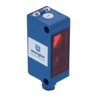
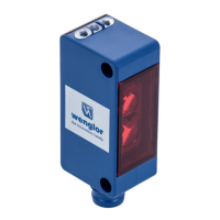
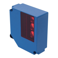
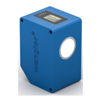
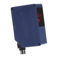
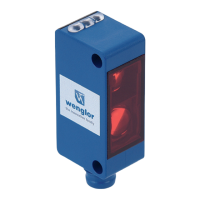
Shows dimensional drawings and key features of the sensor models.

3.5 Control Panel

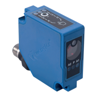
Describes the components of the sensor's control panel and their functions.

3.6 Scope of Delivery

Lists the items included in the product's delivery package.

Transport and Storage

4.1 Transport

Instructs on inspecting the product for damage upon receipt and handling transit damage.

4.2 Storage

Provides guidelines for proper storage conditions to prevent damage and ensure product integrity.

Installation and Electrical Connection

5.1 Installation

Covers essential steps for installing the sensor, including protection and secure mounting.

5.2 Electrical Connection

Details the wiring diagram and pin assignments for connecting the sensor.

5.3 Diagnostics

Explains how to interpret diagnostic indicators and resolve common error conditions.

Settings

Teach-In for Switching Output 1

Describes the procedure for teaching the switching distance for the first output.

Teach-In for Switching Output 2

Details the process for teaching the switching distance for the second output.

Settings via IO-Link

7.1 Teach Mode

Explains the sensor's teach mode functionality for setting switching distances via IO-Link.

7.2 Pin Function, I;O2

Describes how to configure the I/O2 pin as an input or output and its functions.

7.3 Additional functions and settings via IO-Link

Lists advanced functions and parameters configurable through the IO-Link interface.

I;O-Link

Maintenance Instructions

Proper Disposal

Appendix

11.1 List of Abbreviations

Provides a glossary of abbreviations used throughout the operating instructions.

11.2 Change Index, Operating Instructions

Lists revisions and changes made to the operating instructions over different versions.

11.3 EU Declaration of Conformity

Directs users to find the EU Declaration of Conformity document on the manufacturer's website.

Overview

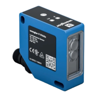
This document describes the P1KHxxx series of reflex sensors with background suppression, featuring high-end performance and teach-in functionality, manufactured by wenglor sensoric elektronische Geräte GmbH.

Function Description

The P1KHxxx reflex sensors operate on the principle of angular measurement, analyzing light reflected from objects. This design minimizes the influence of an object's color, shape, and surface characteristics on the detection range, allowing for reliable detection of even dark objects against a bright background. The sensor switches its output when an object enters the selected range. These sensors are designed for a wide array of industrial applications, including special machinery manufacturing, heavy machinery manufacturing, logistics, automotive, food, packaging, pharmaceuticals, plastics, woodworking, consumer goods, paper, electronics, glass, steel, aviation, chemicals, alternative energy, and raw materials extraction.

The sensors are not safety components according to 2006/42/EC (Machinery Directive) and are not suitable for use in potentially explosive atmospheres. They should only be used with wenglor-supplied or approved accessories and products.

Important Technical Specifications

Optical Data:

  • Service life (ambient temp. = +25 °C): 100,000 hours
  • Max. permissible ambient light: 10,000 Lux
  • Switching Hysteresis: <10%

Electrical Data:

  • Supply power: 15...30 V DC
  • IO-Link supply voltage: 18...30 V DC
  • Temperature drift: <5%
  • Temperature range: -40...60 °C
  • Switching output voltage drop: <2V
  • Switching output switching current: 100 mA
  • Switching output residual current: <50 μA
  • Short-circuit protection: Yes
  • Reverse polarity protected: Yes
  • Overload-proof: Yes
  • Lockable: Yes
  • Interface: IO-Link (version 1.1)
  • Protection class: III
  • Current consumption: <20 mA

Mechanical Data:

  • Setting method: Teach-in
  • Housing material: Plastic
  • Degree of protection: IP67/IP68
  • Lens cover: PMMA
  • Connection: M8x1

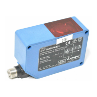
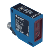
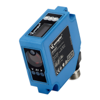
Specific Models (P1KH series):

  • P1KH016, P1KH024:
    • Range: 200 mm
    • Adjustable Range: 30...200 mm
    • Light Source: Red Light
    • Spot Diameter: See Table 1 (e.g., 9 mm at 30 mm range, 7 mm at 120 mm range, 10 mm at 200 mm range)
  • P1KH017, P1KH031:
    • Range: 120 mm
    • Adjustable Range: 30...120 mm
    • Light Source: Laser (red), Laser Class 1 (EN 60825-1)
    • Spot Diameter: See Table 2 (e.g., 2.5 mm at 40 mm range, 1.5 mm at 80 mm range, 1 mm at 120 mm range)

Output Functions:

  • PNP, NPN, NC/NO antivalent, Configurable options available depending on the model.

Switching Frequency / Response Time:

  • Standard Mode (2 independent switching outputs): 100 Hz switching frequency, 5 ms response time (preset configuration)
  • Standard Mode (1 switching output): 1000 Hz switching frequency, 0.5 ms response time
  • Interference-free Mode (2 independent switching outputs): 50 Hz switching frequency, 10 ms response time
  • Interference-free Mode (1 switching output): 500 Hz switching frequency, 1 ms response time

Usage Features

Installation:

  • The sensor must be protected from contamination and mechanical influences during installation.
  • All applicable electrical and mechanical regulations, standards, and safety rules must be observed.
  • The sensor should be mounted securely, adhering to specified torque values (e.g., M3 screws at 0.5 Nm).

Control Panel:

  • The sensor features a control panel with:
    • Switching distance adjuster A1 (5a)
    • Switching distance adjuster A2 (6a)
    • Teach Button (06)
    • Supply power indicator (68)

Teach-in Mode: The switching distance can be taught in for both outputs using the teach-in key on the sensor.

  • Teach-In for Switching Output 1 (Foreground Teach-In by default):
    1. Mount the sensor.
    2. Press and hold the teach-in key until LED A1 blinks.
    3. Release after 2 seconds.
    4. LED A1 lights up to confirm successful teach-in.
  • Teach-In for Switching Output 2:
    1. Mount the sensor.
    2. Press and hold the teach-in key until LED A2 blinks.
    3. Release after 5 seconds.
    4. LED A2 lights up to confirm successful teach-in.
  • Foreground Teach-In: The sensor focuses on the object, and the switching distance is set slightly greater than the clearance between the sensor and the object. This activates the sensor for objects at or closer than the taught distance.
  • Background Teach-In: The sensor spot is aligned to the background, and the switching distance is set slightly less than the clearance to the background. This activates the sensor when an object is located between the background and the sensor.

Pin Function, I/O2 (Configurable):

  • Input External Teach-In:
    • Set E/A2 pin function to external teach-in.
    • With Ub setting active: Apply 18-30 V to E/A2 for 1-4 seconds. A1 is taught in when voltage drops.
    • With Ub setting inactive: Disconnect I/O2 or connect to 0 V for 1-4 seconds. O1 is taught in when voltage is applied.
  • Locking: Continuous activation of the teach-in input locks the teach-in key, protecting against inadvertent changes.
  • Error Output: The error output switches in cases of contamination, aged emitter diode, unreliable working range, short-circuit, over-temperature, or hardware error.

Settings via IO-Link: Further functions and settings can be configured via the IO-Link interface, including:

  • PNP/NPN/push-pull
  • NC/NO
  • Switching hysteresis
  • On/off-delay
  • Operating mode
  • Switch emitted light off
  • Test mode
  • Data storage
  • Process and parameter data, as well as the IODD, are available on the wenglor website.

Diagnostics (Contamination Warning - blinking LED):

  • Continuous blinking at approx. 2.5 Hz:
    • Contamination: Clean the optic cover.
    • Aged emitter diode: Replace the sensor.
    • Unreliable working range: Increase switching distance or reduce distance between sensor and object.
    • Short-circuit: Check electrical wiring and eliminate the short-circuit.
  • Continuous blinking at approx. 5 Hz:
    • Over-temperature: Disconnect power, allow to cool.
    • Hardware error: Replace the sensor.

Maintenance Features

  • The wenglor sensor is maintenance-free.
  • Regular cleaning and inspection of plug connections are advisable.
  • Do not clean the sensor with solvents or cleansers that could damage the product.
  • The product must be protected against contamination during initial start-up.

Proper Disposal:

  • wenglor sensoric GmbH does not accept returns of unusable or irreparable products. Disposal must comply with national waste disposal regulations.

Wenglor P1KH Series Specifications

General IconGeneral
BrandWenglor
ModelP1KH Series
CategoryAccessories
LanguageEnglish

Related product manuals