AM 334-01-502
6
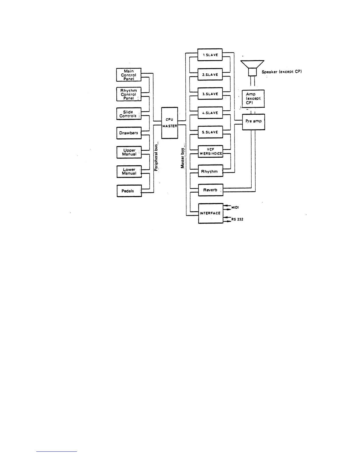
Fig. 1: Block diagram of the DX 400/500 organ series
At the same time, the envelope control DAC (left, Fig. 2)
converts digital data to envelope control voltages for the
eight voice components. The 8-channel multiplex sample
and hold circuitry routes these voltages to the signal DAC's,
which, as multiplying DAC's, directly set the volumes of the
instantaneous analog signals.
The crosspoint matrix routes the analog (audio) signals to
the desired audio bus channels.
3. Audio Block Diagram
The audio signals from the slaves are routed to five audio
channels, Fig. 3, where they undergo various types of
processing:
a) Superdeemphasis (superlowpass) - For bass
voices,
b) Deemphasis (lowpass) channel - For "round"
tone voices, such as drawbars
c) Direct (bright) channel - Slave audio passes
unchanged to the amplifiers
d) VCF channel - Processing for VCF effects
such as wah wah
e) Wersivoice channel - Complex multiple voice
processing; string choir, for example
The functional sequencing of the VCF and Wersivoice is
controlled by the master CPU.
 Loading...