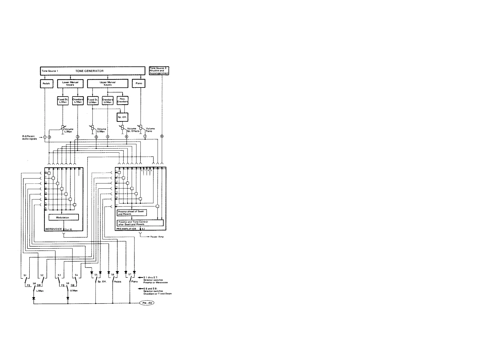
Figure 2 Block diagram of the audio wiring and associated DC controls
3 Initial Operation and
Adjustments
We suppose that power supply, tone generator and electronic keyers have
passed the previous tests and are in good working order (see chapter G II). We
further assume that the organ is equipped with an operating power amplifier
(built-in for W 1 S /external for W 1 T, connected to jack "Output" on AP 2).
Only some of the connectors of the wiring harness G O 1 are to be connected at
this point in time. If in doubt, verify which ones are to be plugged in by rereading
chapter H IV.
3.1 Preparations
Cut off a 100 cm (40") long piece of hookup wire (any color). Solder an alligator
clip to one end and connect the other end to -15V of the power supply (together
with the large number of blue wires).
This lead will serve as test wire to activate the various analog audio switches.
3.2 Conventions and Initial Conditions
A tongue tab is said to be "OFF" when it is in its upper position.
A rocker tab is considered "OFF" when it is sloping down towards the rear
(rear portion pushed down).
A drawbar is "OFF" when it is pushed home.
( )Turn off all tongue tabs and rocker tabs.
AM 071 (Part)
5
 Loading...