CONNECTING RODS AND
PISTONS
Overhaul 12.17.10
Connecting rods 1
to
5 and 10
to
12
Pistons 1
to
9 and 12
I
NA
2 Drain
the
sump.
3 Drain
the
cooling system.
4 Remove the cylinder head gasket, see
12.29.02.
5 Remove and separate
the
connecting
rods and pistons, see 12.17.0
I.
6 Remove
the
rings from
the
pistons.
7 Check
the
jJiston ring gaps, in
an
unworn
part
of
the
cylinder bore,
against
the
figures'
in DAT
A.
If
necessary, increase
the
gap(s)
by
filing
the
end
of
the ring(s).
S Fit
the
piston rings, noting:
a Fit
the
oil control ring
expander
spring first, ensuring
that
the
latch pin enters
both
ends
of
the
spring.
b Fit
the
oil
control
ring with its
gap
ISO
o
from
the
expander
latch
pin.
c Fit the second ring with
the
word
'TOP'
uppermost.
DATA
Connecting
rod
alignment
Maximum out-of-parallel
of
big-end and
little-end
..................
.
Connecting
rod
bush
Clearance
on
gudgeon.pin
........
.
Inside diameter (reamed
after
fitting)
..
Piston rings
Fitted
gap:
Top
compression
Second compression .
Oil
control
........
.
Ring
to
groove clearance:
Top
compression
............
.
Second compression
..........
.
Oil
control
................
.
~r1I'·
O;=II~~
J~LJ~
) B
o~
4NCQ1,
9 Check
the
piston ring groove clearance
against
the
figures in DATA.
10 Check the gudgeon pin clearance in
the connecting rod bush (see DATA).
If
the
clearance
is
excessive, renew
the
bush, noting:
a Position
the
bush with its hole
and oil grooves towards the top.
b Finish-ream
the
bush
to
the
dimension given in DATA.
II
Ensure
that
the
connecting
rod
alignment
is
within
the
figure given in
DATA.
12 Reverse
the
procedure in I
to
5.
0.004
in per inch
(0.004
cm per
cm)
effective mandrel length
0.0002
to
0.0009
in
(0.02
to
0.04 mm)
1.0002
to
1.0007 in (25.41
to
25.42 mm)
0.012
to
0.017 in (0.30
to
0.43 mm)
0.009
to
0.014
in (0.23
to
0.35 mm)
0.012
to
0.017 in (0.30
to
0.43 mm)
0.0025
to
0.0045 in (0.06
to
0.11 mm)
0.0015
to
0.0035 in (0.04
to
0.09 mm)
0.0015
to
0.0035
in (0.04
to
0.09
mm)
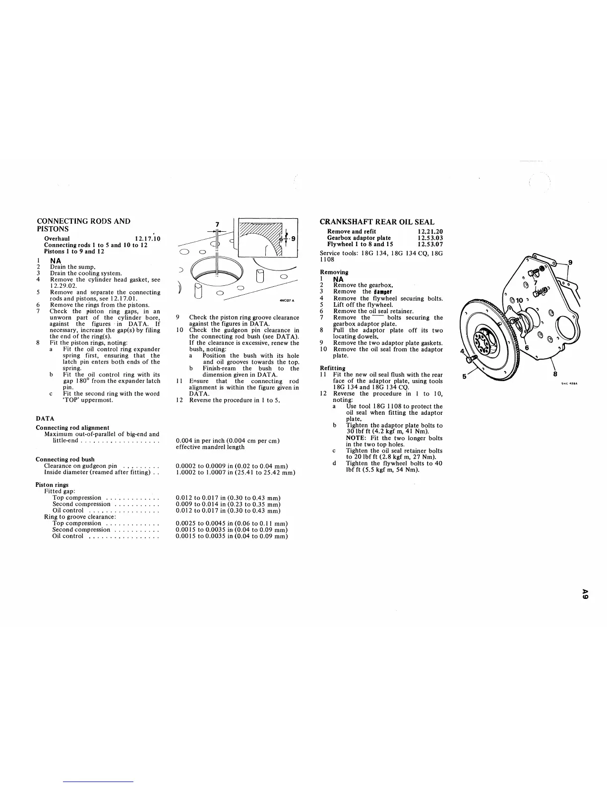
CRANKSHAFT
REAR
OIL
SEAL
Remove
and
refit 12.21.20
Gearbox
adaptor
plate 12.53.03
Flywheel I
to
8
and
IS
12.53.07
Service tools:
ISG
134, ISG 134 CQ, ISG
IIOS
Removing
I
NA
2 Remove
the
gearbox.
3 Remove
the
dllllller
4 Remove
the
flywheel securing bolts.
5 Lift
off
the
flywheel.
6 Remove
the
oil seal retainer.
7 Remove
the
--
bolts securing
the
gearbox
adaptor
plate.
S Pull
the
adaptor
plate
off
its
two
locating dowels.
9 Remove
the
two
adaptor
plate gaskets.
10 Remove
the
oil seal from
the
adaptor
plate.
Refitting
II
Fit
the
new oil seal flush with
the
rear
face
of
the
adaptor
plate, using tools
ISG 134 and ISG 134 CQ.
12 Reverse
the
procedure in I
to
10,
noting:
a
Use tool ISG
II
OS
to
protect
the
oil seal when fitting
the
adaptor
plate.
b Tighten
the
adaptor
plate bolts
to
30lbfft
(4.2
kgfm,
41
Nm).
NOTE: Fit
the
two longer bolts
in
the
two
top
holes.
c Tighten the oil seal retainer bolts
to
20
Ibf ft (2.S kgf
m,
27 Nm).
d Tighten
the
flywheel bolts
to
40
Ibf ft (5.5 kgf
m,
54 Nm).
S,.,C
~18A
l>
CD